A dedicated resistance meter? Here is when it makes sense…

Measuring DC resistances is one of the functions pretty much every bench multimeter provides. Then why you would you need a separate resistance meter?

One of the best digital multimeters available on the market offers a lowest resistance range of 1 Ohm. This feature is highly advantageous for circuit development and PCB testing purposes.

However, when measuring the electrical resistance of conductive materials or welding contacts, you are looking at values which are more in the mOhm or µOhm range.

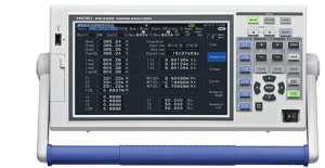
That’s why the “smallest” bench resistance meter from HIOKI – the RM3544 – has the lowest resistance range of 30 mOhm. Its “bigger brother”, the RM3545, has the lowest resistance range of 10 mOhm and a resolution of just 0.01 µOhm.

HIOKI RM3545 Resistance Meter

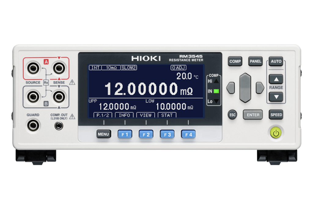
High speed measurements in small resistance ranges

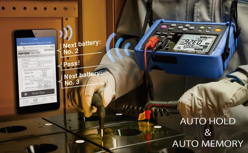
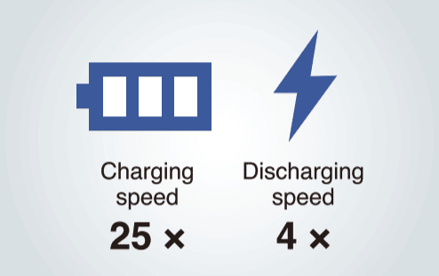
Multimeters are not necessarily optimised to perform measurements at high speed. HIOKI’s resistance meters, on the other hand, have been designed to also perform resistance measurements in mass production environments where speed is an important factor. For example, when a module of lithium-ion batteries is produced then typically the quality of every spot weld connection to the busbar is tested by measuring the contact resistance. The RM3545 can perform such a measurement in its smallest 10 mOhm resistance range in just 41 ms (fast mode). In higher resistance ranges the measurement time is as low as 2.2 ms.

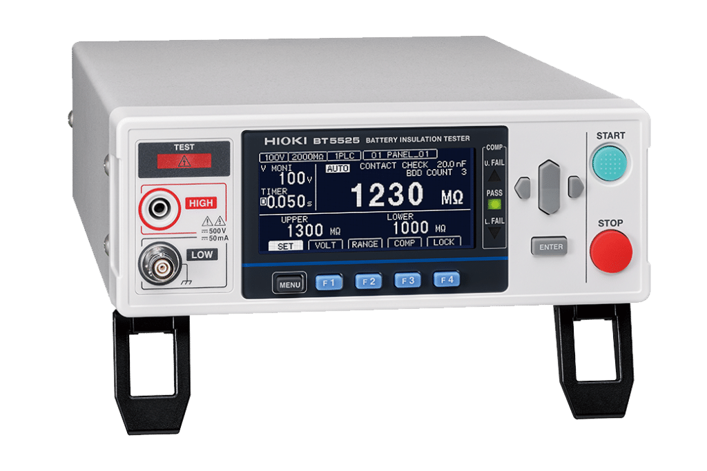
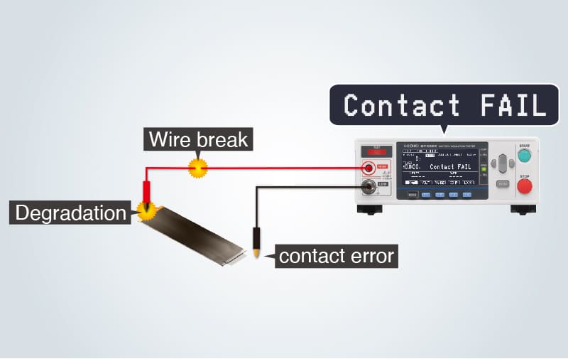
A very useful function (which is hard to find, even in top-of-the-range multimeters) is a contact check function. If activated, a measurement is only started after ensuring that the probe has proper contact to the device under test. This is a feature not necessarily critical in a lab environment, but really useful in production environments where it helps to avoid rejects caused by poor contact of the probe to the DUT. Please note, the contact check function is available on the RM3545, but not the RM3544 or RM3544-01.

Coming back to the example with the busbar welds of the battery module

The longest time in a test process is needed for mechanically moving the DUT to the test probe or test fixture. Once positioned, you want to perform as many tests as possible before having to mechanically move the DUT again.

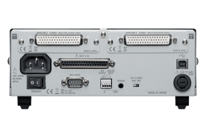
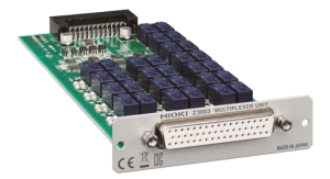
This is where multiplexers come into play, especially when the number of tests to be performed is high. Dedicated multiplexers like HIOKI’s SW1002 provide the required number of measurement channels. If the number of channels is 20 or less, then such a dedicated multiplexer unit isn’t required.

In this case the RM3545-02 offers two slots on the backside that can each hold a multiplexer card Z3003. Each of these multiplexer cards offers 10 measurement channels for 4-wire measurements and they can easily be added to the RM3545-02 models. Please note, you can only add multiplexer cards to the RM3545-02 model.

Backside of RM3545-02 (including two Z3003 multiplexer cards)
Z3003 multiplexer card

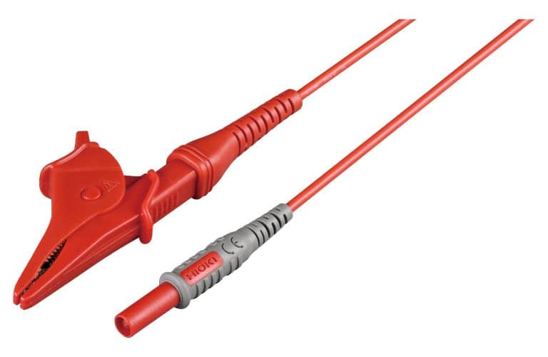
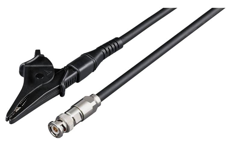
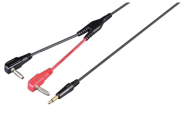
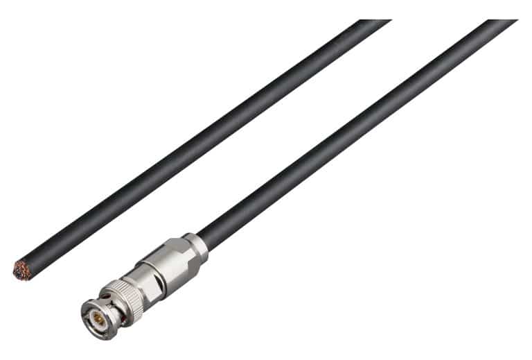
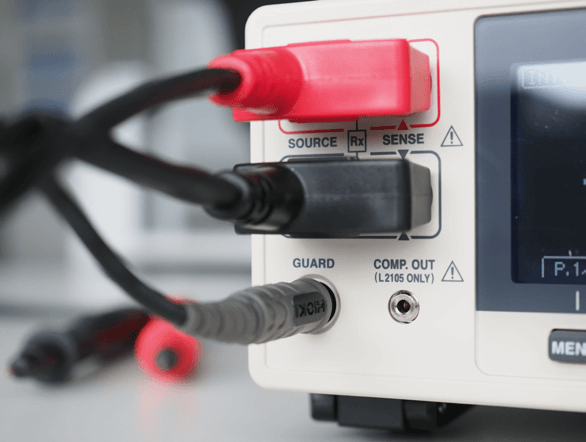
4-wire measurements usually mean 4 connectors at the measurement instrument for the test lead. However, if you look closely at the RM3544 or RM3545 you will see 5 connectors instead of 4. The 5th connector is the so-called “guard terminal”, which is designed to reduce measurement noise that can become relevant especially when test currents are small, i.e. in the high resistance ranges.

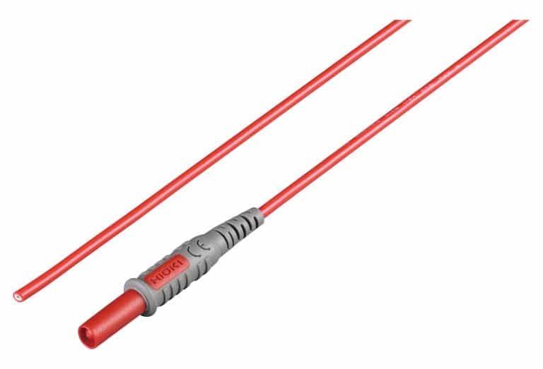
Technically the guard terminal allows to “ground the shield” of the test lead. The guard terminal is supported in HIOKI’s test leads L2101L2102 , L2103 and L2104. Of course, you can also use test leads with the RM3544 and RM3545 that don’t connect to the guard terminal, such as HIOKI’s test leads L2100 or L2107.

Especially when you intend to measure small resistances then the test currents are high and the impact of noise is low. But again, especially in the MOhm resistance ranges not using the guard terminal can impact the measurement results.

Guard terminal: More stable measurements in high resistance ranges

The temperature sensor Z2001 is not just a nice add-on that allows you to also read the temperature when making a resistance measurement. Instead, it corrects the measured resistance value by taking into account a user-specific resistance temperature coefficient. This is especially useful when measurements can’t be performed in a temperature controlled environment.

The Z2001 temperature sensor is an included accessory of the RM3545 models and an option for the RM3544.

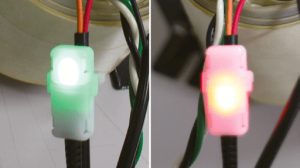
Another useful accessory - LED Comparator Attachment L2105

It indicates judgment results with green and red LEDs, eliminating the need to look at the instrument’s screen. Since the lamps do not light up when the measurement leads are open, this little optional accessory can also be used to ensure a proper connection to the DUT.

L2105 LED Comparator Attachment

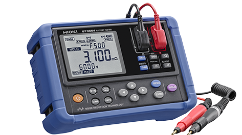
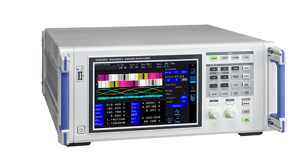
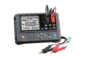
And finally, should you have an application which does require a measurement instrument with a low resistance range but at the same time doesn’t allow you to use a bench resistance meter, then HIOKI’s RM3548 might be the solution, it is portable, yet still features a smallest resolution of just 1 µOhm and offers a smallest measurement range of only 3 mOhm.

HIOKI RM3548 Portable Resistance Meter​

The portable resistance meter RM3548 from HIOKI

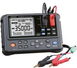
The RM3548 doesn’t feature a guard terminal, as this portable resistance meter is typically used for lower resistances. Lower resistances mean that predominantly higher measurement currents are used for the measurements, making the “grounding of the shield” of the test lead unnecessary.

Also, while the above mentioned RM3545 resistance meter has a largest resistance range of 1200 MOhm, the RM3548‘s largest resistance range is “just” 3.5 MOhm.

Like the bench models RM3544 and RM3545, the RM3548 also supports the L2105 Comparator Attachment. And like the bench models the RM3548 offers a temperature correction and temperature conversion function. That said, bear in mind that the temperature sensor for the RM3548 is called Z2002, which is a different one than the Z2001 used for the bench models.

Conclusion

Multimeters without any doubt offer a huge range of functions that make it one of the most important test tools on a lab bench. At the same time there are requirements where dedicated resistance meters can make a real difference.

Downloads

HIOKI RM3545 Resistance Meter

HIOKI RM3545 Resistance Meter

HIOKI-RM3545-Resistance-Meter

HIOKI RM3548 Portable Resistance Meter

MDL's range of Hioki Resistance Meters

Measuring resistance is essential in the design, development, and maintenance of electrical circuits and systems. 

As official HIOKI distributors for the UK & IE, MDL Technologies offers a wide range of HIOKI Resistance Meters and Battery Testers. View our full range below. Alternatively, you can contact a member of our team for expert technical advice and product support.

Understanding Voltage Fluctuations with Hioki Power Quality Analysers

Voltage fluctuations are a pervasive issue in the world of electrical systems, affecting a wide range of industries and applications. These fluctuations can lead to equipment damage, reduced efficiency, and production interruptions, resulting in significant financial losses.

However, with the right tools and proactive measures, you can effectively manage voltage fluctuations. In this comprehensive guide, we’ll explore the complexities of voltage fluctuations, their impact on various sectors, and how Hioki Power Quality Analysers play a pivotal role in addressing these issues.

Understanding Voltage Fluctuations

There are various types of voltage fluctuations to consider.

Voltage Dips/Sags

Short-term reductions in voltage below the standard level. They can cause equipment malfunctions, disruptions in sensitive processes, and data loss.

Voltage Swells

Temporary increases in voltage above the standard level. These can lead to the overheating of equipment, resulting in premature failure.

Voltage Spikes

Sudden, brief increases in voltage. They can cause immediate damage to sensitive electronics and lead to equipment breakdown.

Voltage Interruptions

A complete loss of voltage for a short period. These can result in downtime and production losses.

Harmonics

Harmonics are frequency components of the voltage waveform that deviate from the ideal sinusoidal waveform. They can lead to overheating of motors and transformers, impacting equipment longevity.

The Impact of Voltage Fluctuations

Voltage fluctuations can have a profound impact on various industries, with some examples affecting personal safety or critical infrastructure resources.

In manufacturing settings, voltage fluctuations can disrupt production lines, leading to costly downtime and product defects. Whilst in Data Centre environments that are sensitive to voltage fluctuations, critical IT equipment can be affected by even minor disturbances that lead to data corruption or system failures.

For commercial buildings, voltage fluctuations can affect lighting systems, elevators, HVAC, and other critical building information systems, leading not only to discomfort and inconvenience for occupants but also costly repair and maintenance tasks for landlords.

In healthcare facilities, voltage fluctuations can affect the operation of medical equipment and life-support systems, posing serious risks to patient safety.

For renewable energy applications like solar and wind farms, energy generation and overall grid stability can be impacted.

Hioki Power Quality Analysers: A Comprehensive Solution

Hioki Power Quality Analysers are advanced instruments designed to monitor and analyse the quality of electrical power. They provide a multifaceted approach to addressing voltage fluctuations and other power quality issues:

  • Continuous Voltage Monitoring: Hioki Power Quality Analysers continuously monitor voltage levels in real-time, ensuring that even the shortest fluctuations are captured.
  • Event Logging: These analysers record and log voltage events, providing valuable data about the frequency, duration, and magnitude of fluctuations.
  • Waveform Analysis: Hioki Power Quality Analysers offer detailed waveform analysis, enabling users to examine the precise characteristics of voltage fluctuations.
  • Harmonics Analysis: In addition to voltage fluctuations, these analysers detect and analyse harmonics, which can be a source of voltage issues and equipment damage.
  • Data Recording: These analysers store extensive data logs, allowing users to review historical data to identify patterns and root causes of voltage fluctuations.
  • Report Generation: Hioki Power Quality Analysers generate comprehensive reports summarizing voltage quality over specific time periods. These reports are useful for compliance reporting and troubleshooting.

Addressing Voltage Fluctuations with a Hioki Power Quality Analyser

Voltage fluctuations are a critical concern in various industries, and their impact can be far-reaching, affecting equipment performance, safety, and overall operational efficiency.

However, with the aid of Hioki Power Quality Analysers, engineers can effectively monitor, analyse, and mitigate voltage fluctuations. By leveraging the capabilities of these analysers, they can ensure the reliability and safety of their electrical systems, minimise risks, and ultimately, enhance their bottom line.

Managing voltage fluctuations isn’t just a reactive approach; it’s a proactive investment in the longevity and efficiency of electrical systems across industries.

With the data and insights provided by a Hioki Power Quality Analyser, engineers can take the following actions to address voltage fluctuations effectively:

  • Identify Root Causes: Analyse the collected data to pinpoint the root causes of voltage fluctuations. These may include issues with the power supply grid or internal electrical system problems.
  • Implement Voltage Stabilization: Based on the analysis, organisations can implement voltage stabilisation measures such as voltage regulators or uninterruptible power supplies (UPS) to protect sensitive equipment.
  • Scheduled Maintenance: Develop a proactive maintenance plan based on data trends. Regular maintenance and equipment checks can prevent voltage fluctuations caused by deteriorating components.
  • Compliance: Ensure compliance with voltage quality standards and regulations. Hioki Power Quality Analysers can help organizations demonstrate compliance with these standards, avoiding potential fines and penalties.
  • Proactive Problem Solving: Address voltage fluctuations before they lead to equipment damage or operational disruptions. A proactive approach can save time and money in the long run.

Streamline Data Centre UPS Battery Maintenance with the Hioki BT3554

For data centre engineers looking to measure the internal resistance and battery voltage of lead-acid batteries supporting UPS back-up power systems, Hioki’s BT3554 Battery Tester provides a quick, simple and feature-rich solution for helping to streamline engineer workflow.

The BT3554 series of portable battery tester is capable of helping to evaluate battery deterioration without having to disconnect or isolate the batteries and sets the standard for assessing the remaining life of UPS and other lead-acid batteries by giving a complete diagnosis via battery resistance testing.

There is a direct correlation between the internal resistance and the discharge capacity of the battery. Data centre engineers can therefore manage the UPS battery system by identifying and recording each battery’s voltage and resistance over time.

The BT3554 can store multiple reference values that can be set as limits to accommodate the many different impedance levels of UPS batteries. These limits are used to compare with the actual impedance and flag a warning or fail status.

Separate profiles can be assigned in the B3554 for different UPS measurement sites, noting battery set locations and UPS, the number of batteries in the set and storage IDs. The measurements taken are then directly linked to the location and battery identity reducing time and the opportunity of error collating the data.

The BT3554 is also compatible with the Hioki Gennect Cross app, linking via Bluetooth to a mobile phone or tablet. Users can then select the relevant profile from the software, and assign a threshold for the voltage and resistance measurement. Once the measurements on the bank of batteries is started, the meter automatically triggers when contact is made with the battery. The mobile device can advise users of a pass/fail and then provide a prompt to move to the next battery in the sequence.

The engineer does not need to refer to the BT3554 display or mobile device during testing. Upon completion, a report can be generated instantly using the profile information and collated test data.

Similarly, with the Gennect One PC app, profiles can be created and loaded onto the BT3554 via USB. The battery tester is then used as a stand-alone device with the measurement sequence and measurement results displayed on the tester’s built-in display. Once the testing is complete, users can reconnect the BT3554 to their PC for instant generation of a report using the profile information and test data.

The Hioki BT3554 series of battery testers can streamline battery maintenance processes by speeding up testing, organising and collating multiple battery test results. With results delivered in as little as 2 seconds and the automatic saving of test results, engineers typically report a 60% reduction in testing times compared to using legacy Hioki products. Screen and audio guidance simplifies the measurement process and data is easily transferred to user’s smartphone, tablet or PC via available software.

Hioki BT3554 Key Features

  • Battery measurement can be performed while the battery is connected to its host device, without taking it offline
  • Instantaneously diagnose battery degradation (PASS, WARNING, FAIL) by measuring internal resistance and voltage
  • Noise reduction technology improves noise resistance
  • A new protector delivers better ergonomic hold and durability during use in the field

BATTERY INSULATION TESTER BT5525

Detect contamination that could cause defects. Improve battery cell productivity through high-speed testing.

To ensure the longevity and reliability of batteries, it is important to identify and address the root causes of latent defects during the production testing process. Small insulation defects, if left unchecked, can have a significant impact on the overall service life of a battery and increase the risk of fires. Two primary factors that contribute to insulation defects are contamination with metallic particles and small scratches that occur during the manufacturing process. By identifying and addressing these issues early on, we can ensure that the batteries produced meet the necessary quality standards and provide safe and reliable performance.

The BT5525 can prevent the shipment of batteries with latent defects that could lead to fires.

High-speed testing to increase production volume. Easy to add instruments while saving space. Invest in quality at a reasonable cost.

Ideal for insulation resistance testing before battery electrolyte filling

The BT5525 conducts insulation testing between electrodes prior to filling the cells with electrolyte, with a maximum test voltage of 500 V. Under specific test conditions, it also facilitates insulation testing between module/pack electrodes and the enclosure.

Detecting minuscule insulation defects caused by contamination (Break Down Detect function)

The proprietary BDD testing function is designed to detect even the smallest internal short-circuits caused by contaminants, such as metallic matter, before the battery cells are filled with electrolyte. By catching defective parts early on in the production process, the BDD helps reduce the risk of fires and accidents caused by overheating after the battery is shipped. Moreover, these tiny internal short-circuits can speed up battery degradation. By using the BDD function, the production of batteries with improved durability and electrical performance can be achieved.

Stable insulation resistance testing, even in noisy environments

Hioki utilized its extensive design expertise and insulation resistance tester measurement technology to successfully minimize the impact of external noise. This has led to the BT5525 delivering stable and consistent insulation resistance testing with a level of precision that allows for the detection of internal short-circuits caused by contamination.

Preventing testing do-overs due to erroneous judgments

The BT5525 offers a contact check function to verify that proper contact has been made with the circuit being tested. This is accomplished by measuring the capacitance between the measurement terminals, which includes both the stray capacitance and the capacitance of the circuit itself.

Ideal for insulation resistance testing before battery electrolyte filling

The BT5525 performs insulation testing between electrodes prior to the cells being filled with electrolyte, with a maximum test voltage of 500 V. In certain conditions that meet the requirements, it can also conduct insulation testing between the module/pack electrodes and the enclosure.

Shorten cycle times with a maximum charging current of 50 mA

The BT5525 boasts fast charging capabilities of up to 50 mA and rapid discharging of residual charge at 40 mA, significantly enhancing its charging and discharging performance.


This results in a boosted testing speed, with charging being approximately 25 times faster and discharging 4 times faster compared to earlier models. By doing so, it shortens the insulation resistance testing time for batteries, which are increasingly being produced with higher capacities.


*In comparison to Hioki’s INSULATION TESTER ST5520.

Compact footprint makes it easy to integrate the BT5525 into other systems

With its extensive product design expertise, Hioki has achieved high performance in a compact form factor. The instrument can be integrated into testing systems, thereby reducing their size. This enables manufacturers to utilize compact testing systems, maximizing limited production space.

Invest in quality at a reasonable cost

The BT5525‘s functionality and performance make it a cost-effective solution, as it was designed with careful consideration given to the specific requirements of battery insulation resistance testing.


A dedicated PC application allows for the monitoring of voltage and current fluctuations during testing.


The instrument has the ability to output a test voltage of up to 500 V, making it suitable for insulation resistance testing on batteries of all sizes, from the large batteries used in electric vehicles to small battery cells.

PC application for analyzing waveforms

Hioki offers a free PC application that allows for the examination of voltage and current fluctuations. The capability to view waveforms can be beneficial when evaluating test results and setting judgment reference values for testing lines.

Additionally, since data can be outputted in the CSV format, waveforms can also be reviewed using other applications, such as Excel.

Options

CLIP TYPE LEAD L2130

For HIGH terminal, banana / alligator clip, red, cord length 1.5m

CLIP TYPE LEAD L2131

For LOW terminal special triaxial / alligator clip, black, cord length 1.5m

OUTPUT CORD L9094

For analog output, banana plugs (red, black), cord length 1.5m

UNTERNIMINATED LEAD L2133

For LOW terminal, special triaxial / cut wire, black, cord length 5m

UNTERMINATED LEAD L2132

For HIGH terminal banana / cut wire, red, cord length 5m

UNTERMINATED LEAD L2132

For external control, double shielding, 9-pin / 9-pin, cord length 3m

Key Features

Contact check function reduces the number of false negatives caused by equipment issues.

BDD function for detecting minuscule short-circuits caused by contamination before batteries are shipped.

High cost performance thanks to accessible pricing, high-speed testing, and compact footprint.

Stable insulation resistance testing even in noisy environments.

Ideal for battery production lines.

Product Video

Dimensions and mass

215 mm (8.46 in) W × 80 mm (3.15 in) H × 306.5 mm (12.07 in) D, 2.8 kg (98.8 oz)

Using AR functionality

Scan the QR Code to the left on your Android or iOS device to access this page. Then select the AR button in the 3D model area to start your AR experience.

[ Precautions ] What you see in AR may differ from the actual product in terms of characteristics like size, colors, and materials. The following operating systems and browsers are recommended. [ iOS ] Safari on iOS 15 or later [ Android ] Chrome on Android 12 or later (AR enabled device)

To assure battery quality over the long term, it’s necessary to detect the causes of latent defects in testing processes on production lines. Minuscule insulation defects can eventually degrade battery service life and cause fires. The principal causes of insulation defects are contamination (with metallic matter) and minuscule scratches occurring in production processes.

The BT5525 can prevent the shipment of batteries with latent defects that could lead to fires.

This is introduction to the functions of the new “BATTERY INSULATION TESTER BT5525” for battery production lines. The BDD function, which monitors minute voltages and currents and detects foreign substances mixed in the production process, and a convenient PC application that allows you to view waveforms, will be explained while actually measuring!

Interface

Front Interface

Back Interface

External control and other communications interfaces

The BT5525 ships standard with LAN, RS-232C, and USB interfaces, allowing it to be connected to a PC or programmable logic controller (PCL). This capability can be used to control the instrument and retrieve test results.

Furthermore, the instrument provides external I/O terminals to facilitate instrument control and retrieval of instrument status and judgment results.

Accurately Measure High Voltages up to 5000 V in a Variety of Applications with the new Hioki VT1005

The new Hioki VT1005 high voltage divider accepts input voltages up to 5kVrms /4MHz for accurate power measurements

In order to meet the continuous need for more electrical power, there is a trend to introduce higher system voltages in a wide range of applications. One particular application is the accurate efficiency measurement of railways, trucks and busses that are operating at voltages higher than 1000V. Accurate power loss measurement of inductive components used in HV power electronics is another interesting application.

Engineers prefer to measure the loss in these devices under real-life conditions and the very low power factor of these measurements requires a phase error compensation to achieve accurate measurements. This can be discovered with the Hioki High Voltage Divider.

SiC semiconductors are increasingly used for high-voltage applications with switching frequencies of 50kHz or higher. The VT1005 High Voltage Divider is the only solution on the market today that is designed to provide accurate results even at these high switching frequencies.

The VT1005 High Voltage Divider provides the best solution for accurate power measurement up to 5kVrms and 4MHz in combination with the Power Analyser PW8001.

Hioki VT1005 High Voltage Divider Highlights

  • Input Voltage up to 5kVrms / 7.1kVpeak
  • Voltage dividing ratio is 1000:1
  • Measurement bandwidth 4MHz
  • Identical gain and phase characteristics for each divider
  • Phase error compensation with PW8001 (firmware version 1.3 or higher)
  • Excellent frequency flatness needed for high‐efficiency inverter measurements

Learn more about the Hioki VT1005

To talk to a member of our team about the new Hioki VT1005,
call us on +44 (0)1462 431 981.

HIOKI’s new Power Analyzer PW8001 provides complete power analysis solutions

HIOKI sets a new industry standard with its all-new PW8001 Power Analyzer. With up to eight modular power channels, it is the only bench power analyzer on the market with 1500 V DC CAT
II inputs, fulfilling the requirements of today’s PV applications. At the same time, high bandwidth and industry-leading current sensors allow for unrivalled accuracy for example when developing
state-of-the-art SiC and GaN applications.

Best protection against external noise is guaranteed because of the highest Common Mode Rejection Ratio in the industry for both power analyzer and current sensors designed by HIOKI.
In addition, the 15 MHz sampling rate and 18-bit A/D conversion result in extremely accurate measurements and waveform reproducibility.

As unique feature, the automatic phase shift correction function of the PW8001 allows for accurate reactor or transformer loss measurements at high switching frequencies. Optional four motor inputs enable the complete analysis of multiple motor systems like drones, robotics or in-wheel motor drive systems of electric vehicles.

Key Features

  •  Up to 8 modular power channels
  • Unrivalled accuracy for high currents at high frequencies
  • Best protection against external noise
  • Automatic phase shift correction
  • 15 MHz sampling rate and 18-bit A/D conversion
  • 1500 V DC CAT II voltage inputs

See the Features: 

[Webinar] Hioki Solutions for Battery Testing

35 years ago HIOKI introduced their first battery tester. Since then a wide portfolio of instruments for all battery testing needs has been established, from battery R&D to production, quality assurance and maintenance.

Find out where insulation testers, resistance meters, impedance analyzers and volt meters come into play in battery testing – and of course battery testers. Collaboration with HIOKI UK partners, MDL Technologies.


Hioki Battery Solutions Webinar: 


Hioki 3-Range AC/DC Wideband Current Sensor Application

In the development of automotive electrical control systems, it is important to measure and validate a diverse array of current levels among components such as:

  • Drive current of various motors in the order of several amperes
  • Inrush current, for example at motor start, in the order of several tens of amperes
  • Minute control signals of about 1 mA
  • Standby current

The need to measure such a wide range, from micro standby currents to inrush currents that can reach tens of amperes traditionally necessitate the use of separate sensors equipped with the appropriate range so that resolution and accuracy are not sacrificed. Using a higher range current sensor to measure low standby current will reveal no meaningful result, while sensors with a low range will not be able to handle high currents safely.

Hioki provides a solution for this particular application with the CT6710 (50MHz bandwidth) and CT6711 (120MHz bandwidth)  current probes (based on the zero-flux current sensing method using Hall Element detection), both of which offer three separate ranges to meet an expansive range of measurements in a single unit. More on this below:


Zero Flux AC/DC Current Sensing using Hall Element

In the zero-flux method, in order to cancel out the magnetic flux produced inside the magnetic core by the AC current flowing in the conductor being measured, a secondary current flows to the secondary side of the feedback winding. The magnetic flux existing in the low-frequency regions that cannot be cancelled is detected using a CT, Hall element, or Flux gate element, upon which a secondary feedback current is generated through an amplifier circuit so as to cancel out the magnetic flux in the low Hz regions. This secondary current flows to the shunt resistor, producing a voltage that is proportional to the current flowing in the conductor being measured.

The Hall element detection method is represented by the Hioki Models 3273-50 , 3274 , 3275 , 3276 , CT6700 , CT6701 , CT6710 , and CT6711 , all of which deliver the following key characteristics:

  • Similar to the CT detection method, sensor operation depends on canceling out the magnetic flux in the magnetic core, giving it excellent linearity unaffected by the magnetic core’s B-H magnetic characteristics.
  • Since the probes operate using the CT of the secondary feedback winding in the high-frequency region, and utilize an amplifier for the low-frequency region, a broad frequency bandwidth is supported.
  • Like the flux-gate element detection method that will be discussed in the next installment, due to lack of excitation current noise, overall noise is extremely low.

Note that:

  • The Hall element used in Hioki current probes is developed and manufactured in-house using a compound semiconductor called indium antimonide (InSb), which while delivering high-sensitivity, is susceptible to temperature drift due to its sensitivity to the surrounding temperature.

Because the zero-flux method achieves extremely stable measurements by driving the negative feedback characteristics of the magnetic circuit, thus reducing the effects of the magnetic core, it is capable of delivering a wide frequency band and improved linearity, factors that contribute to the optimization of the current sensor’s performance. Such characteristics are ideal for these AC/DC applications:

  • Current testing of ECU and instrumentation systems in automobiles, e.g., dark current, large current, operating current of various motors
  • Current consumption testing of wearable devices, e.g., battery-operated devices and their sensors
  • Performance evaluation of high speed switching devices, e.g., monitoring the current waveform of SiC, GaN or other types of advanced components