RadiSwitch is a cutting-edge technology developed by Raditeq, designed to improve the performance and efficiency of RF switches. It features a unique design that enables high-speed switching with minimal signal distortion, making it an ideal solution for a wide range of applications, from telecommunications and wireless networks to military and aerospace systems. With RadiSwitch, users can enjoy greater reliability, reduced power consumption, and improved signal quality, all in a compact and cost-effective package.
RadiSwitch
| Product Name | Max. Frequency Range | Connector type | Life Cycles | Details |
|---|---|---|---|---|
| RadiSwitch® RSW1024V | Max. 67 GHz | 4x SPDT 1.85 mm V-type | 2.000.000 cycles | More Details |
| RadiSwitch® RSW1022V | Max. 67 GHz | 2x SPDT 1.85 mm V-type | 2.000.000 cycles | More Details |
| RadiSwitch® RSW1062Q | Max. 50 GHz | 2x SP6T 2.4 mm Q-type | 2.000.000 cycles | More Details |
| RadiSwitch® RSW1061Q | Max. 50 GHz | 1x SP6T 2.4 mm Q-type | 2.000.000 cycles | More Details |
| RadiSwitch® RSW1024Q | Max. 50 GHz | 4x SPDT 1.85 mm Q-type | 2.000.000 cycles | More Details |
| RadiSwitch® RSS1022Q | Max. 50 GHz | 2x SPDT 1.85 mm Q-type | 2.000.000 cycles | More Details |
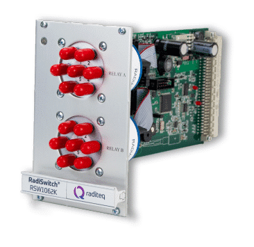
| RadiSwitch® RSW1062K | Max. 40 GHz | 2x SP6T 2.92 mm K-type | 2.000.000 cycles | More Details |
| RadiSwitch® RSW1061K | Max. 40 GHz | 1x SP6T 2.92 mm K-type | 2.000.000 cycles | More Details |
| RadiSwitch® RSW1024K | Max. 40 GHz | 4x SPDT 2.92 mm K-type | 10.000.000 cycles | More Details |
| RadiSwitch® RSW1022K | Max. 40 GHz | 2x SPDT 2.92 mm K-type | 10.000.000 cycles | More Details |
| RadiSwitch® RSW1062S | Max. 18 GHz | 2x SP6T SMA | 5.000.000 cycles | More Details |
| RadiSwitch® RSW1061S | Max. 18 GHz | 1x SP6T SMA | 5.000.000 cycles | More Details |
| RadiSwitch® RSW1024S | Max. 18 GHz | 4x SPDT SMA | 10.000.000 cycles | More Details |
| RadiSwitch® RSW1022S | Max. 18 GHz | 2x SPDT SMA | 10.000.000 cycles | More Details |
| RadiSwitch® RSW1021N | Max. 12,4 GHz | 2x SPDT N-Type | 1.000.000 cycles | More Details |
| RadiSwitch® RSW1021B | Max. 3 GHz | 2x SPDT BNC | 1.000.000 cycles | More Details |
| RadiSwitch® RSW2002E | 8-way Terminal Block | 2x External Relay | NA | More Details |
| Model | Relay | Connector | Max. Frequency |
|---|---|---|---|
| RSW1021B | 1 x SPDT | BNC | 3 GHz |
| RSW1021N | 1 x SPDT | N-type | 12.4 GHz |
| RSW1022S | 2 x SPDT | SMA | 18 GHz |
| RSW1024S | 4 x SPDT | SMA | 18 GHz |
| RSW1061S | 1 x SP6T | SMA | 18 GHz |
| RSW1062S | 2 x SP6T | SMA | 18 GHz |
| RSW1022K | 2 x SPDT | 2.92 mm | K-type | 40 GHz |
| RSW1024K | 4 x SPDT | 2.92 mm | K-type | 40 GHz |
| RSW1061K | 1 x SP6T | 2.92 mm | K-type | 40 GHz |
| RSW1062K | 2 x SP6T | 2.92 mm | K-type | 40 GHz |
| RSW1022Q | 2 x SPDT | 2.4 mm | Q-type | 50 GHz |
| RSW1024Q | 4 x SPDT | 2.4 mm | Q-type | 50 GHz |
| RSW1061Q | 1 x SP6T | 2.4 mm | Q-type | 50 GHz |
| RSW1062Q | 2 x SP6T | 2.4 mm | Q-type | 50 GHz |
| RSW1022V | 2x SPDT | 1.85 mm | V-type | 67 GHz |
| RSW1024V | 4x SPDT | 1.85 mm | V-type | 67 GHz |
| RSW2002E | 2 x external | 8-way terminal block | External relay dependant |
Flexible
RadiSwitch® plug-in cards come in various versions, including one, two, or four SPDT (single pole double throw) coaxial relays or SP6T (single pole six throw) coaxial relays. These versions are available in 18 GHz (SMA type), 40 GHz (k type), 50 GHz (Q type), and 67GHz (V type) models. Additionally, plug-in cards with BNC-type (3 GHz) or N-type (12.4 GHz) connectors are also available.
You can use any combination and quantity of plug-in cards in the RadiCentre®, which makes the system one of the most flexible switching systems in the world.
Hardware interlock
You can connect the RF interlock input to a switch on the access door of the test chamber. This ensures that the interlock is only released when the door is closed, which helps maintain a safe environment for testing.
External switching
The RSW2002E plug-in card has drivers that let you control two external switches, and each relay can handle a current of up to 500 mA. Additionally, the card has an internal power supply that can power the relays of the 12 VDC, 24 VDC, or 28 VDC type.
Control
Both the two- and seven-slot versions of the RadiCentre® have a 7-inch TFT touch screen for manual control and monitoring, but you can also control them from a PC via USB, LAN, or GPIB (optional). Furthermore, you can control both the RadiCentre® and RadiSwitch® using RadiMation® EMC testing software or any other EMC testing software package using device commands.
RadiSwitch® RF Switch Matrixes
The RadiSwitch® series offers a variety of RF switching plug-in cards for fully automated EMC testing. EMC test systems can be complex installations with many different test and measurement instruments. To enable fully automated testing, all measuring instruments and connections between amplifiers, power meters, antennas, and EMI receivers must be selected automatically.
RadiSwitch® is designed specifically to switch RF signals between multiple instruments during EMC and RF measurements. The RadiSwitch® plug-in cards fit into a RadiCentre® modular test system, which is an essential component of the switchgear for all types of EMC and RF tests.
You can easily control the switching cards automatically using EMC test software like RadiMation®. This allows for smoother and more efficient testing processes.
Reliable
Even with continuous use 24/7, 365 days a year, and switching every minute, the RadiSwitch® cards will still last for two years. And in more regular testing situations (10 hours/day, 250 days a year, and switching 10 times an hour), the RadiSwitch® will last for up to 40 years.
(*) The SMA version of the RadiSwitch® has a lifespan of 5-10 million cycles, while the K and W versions can handle up to 2 million cycles.
Easy to use & extendable
The RadiSwitch® system is designed to be “Plug and Play”, which means that every plug-in card is automatically recognized, initialized, and ready to use.
Users can easily configure and control the relay position of each individual RadiSwitch® plug-in card using the touch screen or with EMC testing software. For more extensive switching applications, multiple RadiCentre® EMC systems can be used together.