Introducing the RFScanner, the latest bench-top antenna measurement tool from Y.I.C. Technologies

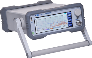
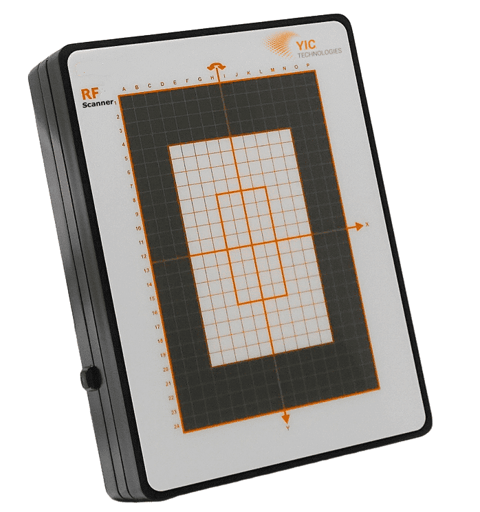
The RFScanner is an Antenna Pattern Characterisation, Measurement and Diagnostic Tool on your Lab-bench.

The Y.I.C. Technologies RFScanner is a compact bench-top scanner that characterises antennas in your own lab environment in real-time. This solution gives insights into the root causes of antenna performance challenges and helps troubleshoot far-field radiation patterns in real-time.

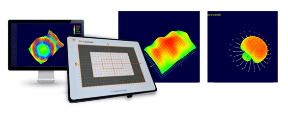
The RFScanner measures the amplitude and phase of near-field magnetic emissions and uses these data provides far-field patterns, bisections, EIRP and TRP and other parameters in seconds.

RFScanner Key Features


  • Frequency Range of 300 MHz to 6.0 GHz
  • Far-Field Patterns and Bisections including EIRP / TRP / PRD, Circular and linear polarisation and axial ratio patterns
  • Near-Field Insights such as Amplitude and Phase distribution available in  seconds
  • Gain, Efficiency and S11 chart with Supported VNAs
  • “Real-time” real-fast
  • Can be used to evaluate either standalone (i.e. passive) antennas or antennas that are embedded in wireless devices (i.e. active antennas).
  • Simple set up and Easy to use


Download Datasheet

RFScanner provides far-field patterns, bisections, EIRP and TRP in seconds. Novel near-field results, including amplitude, polarity and phase give insights into the root causes of antenna performance challenges and help troubleshoot far-field radiation patterns.

To talk to a member of our team about the new Y.I.C. Technologies RFScanner,
call us on +44 (0)1462 431 981.

APM Power Electronics Test

APM Power Electronics Quick Model Selection

Output Voltage1U2U
600W1000W1200W1500W1600W1000W2000W3000W4000W
20VDC60A60A60A******
32VDC50A50A50A*50A200A200A200A200A
40VDC40A40A40A*40A120A120A120A120A
75VDC25A25A25A25A****60A
80VDC*****60A60A60A*
120VDC*****40A40A40A40A
150VDC10A10A10A10A*30A30A30A30A
200VDC8A8A8A8A*24A24A24A24A
600VDC*****10A10A10A10A
800VDC*****7.5A7.5A7.5A7.5A
Output Voltage3U6U
6000W12000W18000W24000W30000W36000W
80VDC200A400A600A800A1000A1200A
165VDC*180A*360A*540A
250VDC**180A***
360VDC42.5A85A127.5A170A212.5A255A
500VDC32A64A96A128A160A192A
750VDC21A42A63A84A105A126A
1000VDC*32A*64A*96A
1500VDC*21A32A42A*63A
2250VDC**21A***
Output Voltage13U Cabinet19U Cabinet27U Cabinet
2 Parallel3 Parallel4 Parallel5 Parallel6 Parallel7 Parallel8 Parallel9 Parallel10 Parallel
8kW12kW16kW20kW24kW28kW32kW36kW40kW
32VDC400A600A800A1000A1200A1400A1600A1800A2000A
40VDC240A360A480A600A720A840A960A1080A1200A
75VDC120A180A240A300A360A420A480A540A600A
120VDC80A120A160A200A240A280A320A360A400A
150VDC60A90A120A150A180A210A240A270A300A
200VDC48A72A96A120A144A168A192A216A240A
600VDC20A30A40A50A60A70A80A90A100A
800VDC15A22.5A30A37.5A45A52.5A60A67.5A75A
Output Voltage6kW9kW12kW15kW18kW21kW24kW27kW30kW
80VDC120A180A240A300A360A420A480A540A600A

*This formula is the standard cabinet for SP-2U model; it is available to select cabinet with different specification according to exact situation. Detail please consults our area manager.

Output Voltage18U Cabinet24U Cabinet30U Cabinet36U Cabinet42U Cabinet
2 Parallel3 Parallel4 Parallel5 Parallel6 Parallel7 Parallel8 Parallel9 Parallel10 Parallel
80VDC36kW54kW72kW90kW108kW126kW144kW162kW180kW
1200A1800A2400A3000A3000A3000A3000A3000A3000A
165VDC24kW36kW48kW60kW72kW84kW96kW108kW120kW
360A540A720A900A1080A1260A1440A1620A1800A
250VDC36kW54kW72kW90kW108kW126kW144kW162kW180kW
360A540A720A900A1080A1260A1440A1620A1800A
360VDC36kW54kW72kW90kW108kW126kW144kW162kW180kW
255A382.5A510A637.5A765A892.5A1020A1147.5A1275A
500VDC36kW54kW72kW90kW108kW126kW144kW162kW180kW
192A288A384A480A576A672A768A864A960A
750VDC36kW54kW72kW90kW108kW126kW144kW162kW180kW
126A189A252A315A378A441A504A567A630A
1000VDC24kW36kW48kW60kW72kW84kW96kW108kW120kW
64A96A128A160A192A224A256A288A320A
1500VDC36kW54kW72kW90kW108kW126kW144kW162kW180kW
64A96A128A160A192A224A256A288A320A
2250VDC36kW54kW72kW90kW108kW126kW144kW162kW180kW
42A63A84A105A126A147A168A189A210A

*Above cabinets are formed with 3U height DC power supplies. Different height cabinets can be connected in parallel to a 576kW system. Please contact APM sales representative for details.

Output Voltage2U3U4U
600W1000W1500W2000W3000W4000W5000W
150VAC/300VAC5.6A/2.8A9.2A/4.6A13.8A/6.9A16A/8A27.6A/13.8A32A/16A46A/23A
Output VoltageOutput Mode2 Parallel
9U Cabinet17U Cabinet
1200W2000W3000W4000W6000W8000W10000W
150VAC/300VAC1 Phase10.08A/5.04A15.56A/8.28A24.84A/12.42A28.8A/14.4A49.68A/24.84A57.6A/28.8A82.8A/41.4A
Output VoltageOutput Mode3 Parallel
9U Cabinet17U Cabinet
1800W3000W4500W6000W9000W12000W15000W
150VAC/300VAC1 Phase15.12A/7.56A24.84A/12.42A37.26A/18.63A43.2A/21.6A74.52A/37.26A86.4A/43.2A124.2A/62.1A
Output VoltageOutput Mode4 Parallel
17U Cabinet21U Cabinet
2400W4000W6000W8000W12000W16000W20000W
150VAC/300VAC1 Phase20.16A/10.08A33.12A/15.56A49.68A/24.84A57.6A/28.8A99.36A/49.68A115.2A/57.6A165.6A/82.8A
Output VoltageOutput Mode2 Series
9U Cabinet17U Cabinet
1200W2000W3000W4000W6000W8000W10000W
300VAC/600VAC1 Phase5.04A/2.52A8.28A/4.14A12.42A/6.21A14.4A/7.2A24.84A/12.42A28.8A/14.4A41.4A/20.7A
Output VoltageOutput Mode9U Cabinet17U Cabinet
1800W3000W4500W6000W9000W12000W15000W
150VAC/300VAC1/3 Phase5.6A/2.8A9.2A/4.6A13.8A/6.9A16A/8A27.6A/13.8A32A/16A46A/23A
Intput Voltage2U3U4U
600W1200W1800W2400W3000W3400W4400W5600W6600W8100W
200VDC60A130A190A260A320A370A480A610A720A720A
600VDC40A90A130A180A220A250A320A410A480A600A
1200VDC*45A*90A*125A160A205A240A300A
Intput Voltage7U10U 
8800W10300W11000W12500W13200W14700W15400W16900W17600W 
200VDC960A960A1200A1200A1440A1440A1680A1680A1920A 
600VDC640A760A800A920A960A1080A1120A1240A1280A 
1200VDC320A380A400A460A480A540A560A620A640A 
Intput Voltage10U13U 
19100W19800W21300W22000W23500W24200W25700W26400W27900W 
200VDC1920A2160A2160A2400A2400A2640A2640A2880A2880A 
600VDC1400A1440A1560A1600A1720A1760A1880A1920A2040A 
1200VDC700A720A780A800A860A880A940A960A1020A 
Intput Voltage30U Cabinet36U Cabinet42U Cabinet
39.6kW44.1kW52.8kW58.8kW66kW73.5kW
200VDC3000A3000A3000A3000A3000A3000A
600VDC2880A3000A3000A3000A3000A3000A
1200VDC1440A1620A1920A2160A2400A2700A

PMM NARDA Reciever Range

Pre-Compliant (P)

Frequency BandsPre-Compliant (P)
       
Test TypeCISPRHz7010/027010/00(*)7010/017010/03
RF Cond.MIL10-9k    
RF Cond.A9k-150kP PP
RF Cond.B150k-30MPPPP
RF Rad.CISPR30M-300M PPP
RF Rad.D300M-1G PPP
RF Rad.E1G-3G   P
RF Rad.E3G-6G    
RF Rad.E6G-18G    

Key:         (P) – Pre-Compliant           (F) – Fully Compliant

Mixed Full (F) / Pre-Compliant (P)

Frequency BandsMixed Full (F) / Pre-Compliant (P)
      
Test TypeCISPRHz9010/03P9010/30P9010/60P
RF Cond.MIL10Hz-9kHzFFF
RF Cond.A9kHz-150kHzFFF
RF Cond.B150kHz-30MhzFFF
RF Rad.CISPR30Mhz-300MhzPPP
RF Rad.D300Mhz-1Ghz PP
RF Rad.E1Ghz-3Ghz PP
RF Rad.E3Ghz-6Ghz  P
RF Rad.E6Ghz-18Ghz   

Key:         (P) – Pre-Compliant           (F) – Fully Compliant

Full-Compliant (F)

Frequency BandsFull Compliant (F)
   DigitalFFTFFTFFT9010F or 9010/xxP with
Test TypeCISPRHz9010 (*)9010FER8000/00ER8000/019030906091809060+9180
RF Cond.MIL10-9k  FFFF
RF Cond.A9k-150kFFFFF
RF Cond.B150k-30MFFFFFFF
RF Rad.CISPR30M-300M   FFF F
RF Rad.D300M-1G   FFF F
RF Rad.E1G-3G   FFF F
RF Rad.E3G-6G     F F
RF Rad.E6G-18G      FF

Key:         (P) – Pre-Compliant           (F) – Fully Compliant

Narda presents a comprehensive selection of receivers that adhere to both FULL and PRE compliance standards, equipped with advanced FFT technology. These receivers cover an extensive frequency range from 10 Hz to 18 GHz. They boast compact dimensions while maintaining flexibility and reliability. Additionally, they come with built-in LISN capabilities, enabling seamless execution of conducted and radiated tests in complete accordance with CISPR 16-1-1 and MIL-STD regulations.

  • ER9000 – EMI Riceiver FFT Full-Compliant 10 Hz – 3 GHz  
  • FR-4003 – FFT Full compliance field receiver 9 kHz – 30 MHz
  • 7010 –  Pre compliance receiver 9 kHz – 3 GHz with built-in LISN
  • 9010F – FFT Full compliance receiver 10 Hz – 30 MHz
  • ER8000 – FFT  EMI receiver   9 kHz – 3 GHz  
  • Series 9010/xxP – Full/Pre compliance receivers 10 Hz – 6 GHz
  • CA0010 – Four-channel Click Analyzer with integrated LISN and full CISPR calibrator
  • 9030, 9060, 9180 – External units Full compliance 30 MHz – 18 GHz

Scroll to load!

WaveControl Field Probe Selection

WaveControl Field Probe Selection Graph

SMP3 Versions

WP10M Field Probe

  • 1 Hz – 10 MHz
  • E & H field
  • Selective & Broadband
  • Energy: IEC/EN 62110
  • Railway: EN 50500
  • Welding: EN 50505
  • Induction heating (LF): EN 50519
  • Electric arc or induction smelting
  • Household appliances: IEC/EN 62233, EN 50366
  • RFID/EAS: EN 50364, EN 50357, IEC/EN 62369-1
  • Medical: IEC 60601
  • Research/Labs
  • Electronic/electrical equipment: IEC/EN 62311
  • Defense (LF) 
  • Workplace assessment: EN 50499
  • Assessment of workers bearing AIMDs: EN 50527-1
  • Human exposure assessment: EN 50413
  • Automotive
WaveControl WP10M

Compatible with:

SMP3
SMP3
WaveControl WP50

Compatible with:

SMP3
SMP3
SMP2
MonitEM

WP50 Field Probe

  • 10 Hz – 3 kHz
  • E & H field
  • Broadband
  • Energy: IEC/EN 62110
  • Induction heating: EN 50519
  • Electric arc or induction smelting
  • Workplace assessment: EN 50499
  • Human exposure assessment: EN 50413
  • Other low frequency applications
  •  

WP400 Field Probe

  • 1 Hz – 400 kHz
  • E & H field
  • Selective & Broadband
  • Energy: IEC/EN 62110
  • Railway: EN 50500
  • Welding: EN 50505
  • Induction heating (LF): EN 50519
  • Electric arc or induction smelting
  • Household appliances: IEC/EN 62233, EN 50366
  • RFID/EAS: EN 50364, EN 50357, IEC/EN 62369-1
  • Medical: IEC 60601
  • Research/Labs
  • Electronic/electrical equipment: IEC/EN 62311
  • Defense (LF) 
  • Workplace assessment: EN 50499
  • Assessment of workers bearing AIMDs: EN 50527-1
  • Human exposure assessment: EN 50413
  • Automotive
    •  
WaveControl WP400

Compatible with:

SMP3
SMP3
SMP2
WaveControl WP400

Compatible with:

SMP3
SMP3
SMP2

WP400c Field Probe

  • 1 Hz – 400 kHz
  • E & H field
  • Selective & Broadband
  • Automotive
  • Energy: IEC/EN 62110
  • Railway: EN 50500
  • Welding: EN 50505
  • Induction heating (LF): EN 50519
  • Electric arc or induction smelting
  • Household appliances: IEC/EN 62233, EN 50366
  • RFID/EAS: EN 50364, EN 50357, IEC/EN 62369-1
  • Medical: IEC 60601
  • Research/Labs
  • Electronic/electrical equipment: IEC/EN 62311
  • Defense (LF) 
  • Workplace assessment: EN 50499
  • Assessment of workers bearing AIMDs: EN 50527-1
  • Human exposure assessment: EN 50413
      •  

WP400-3 Field Probe

  • 1 Hz – 400 kHz
  • E & H field
  • Selective & Broadband
  • Assessment of:
      • Welding equipment: IEC/EN 62822, EN 50505
      • Household appliances: IEC/EN 62233, EN 50366
      • Other electronic/electrical equipment: IEC/EN 62311
    • Research/Labs 
    • Other application where small size and spatial resolution is important
    •  
  •  
WaveControl WP400-3

Compatible with:

SMP3
SMP3
SMP2

Compatible with:

SMP3
SMP3
SMP2
MonitEM
MonitEM-Lab

WPF3 Field Probe

  • 100 kHz – 3 GHz
  • E field
  • Broadband
  • Telecommunications:
    • Wireless telecom networks: IEC 62232, EN 50400, EN 50401
    • Broadcast: IEC 62577, EN 50475, EN 50476, EN 50496, EN 50554
  • RFID/EAS: EN 50364, EN 50357, IEC/EN 62369-1
  • Induction heating (HF): EN 50519
  • Plastic welding
  • Semiconductor production
  • Medical: IEC 60601
  • Workplace assessment: EN 50499
  • Assessment of workers bearing AIMDs: EN 50527-1
  • Human exposure assessment: EN 50413
  • Research/Labs
  • Microwave drying

WPF6 Field Probe

  • 100 kHz – 6 GHz
  • E field
  • Broadband
  • Telecommunications:
    • Wireless telecom networks: IEC 62232, EN 50400, EN 50401, EN 50492
    • Broadcast: IEC 62577, EN 50475, EN 50476, EN 50496, EN 50554
  • RFID/EAS: EN 50364, EN 50357, IEC/EN 62369-1
  • Induction heating (HF): EN 50519
  • Plastic welding
  • Semiconductor production
  • Medical: IEC 60601
  • Workplace assessment: EN 50499
  • Assessment of workers bearing AIMDs: EN 50527-1
  • Human exposure assessment: EN 50413
  • Research/Labs
  • Microwave drying

Compatible with:

SMP3
SMP3
SMP2
MonitEM
MonitEM-Lab
WPF8

Compatible with:

SMP3
SMP3
SMP2
MonitEM
MonitEM-Lab

WPF8 Field Probe

  • 100 kHz – 8 GHz
  • E field
  • Broadband
  • Telecommunications:
    • Wireless telecom networks: IEC 62232, EN 50400, EN 50401, EN 50492
    • Broadcast: IEC 62577, EN 50475, EN 50476, EN 50496, EN 50554
  • RFID/EAS: EN 50364, EN 50357, IEC/EN 62369-1
  • Induction heating (HF): EN 50519
  • Plastic welding
  • Semiconductor production
  • Medical: IEC 60601
  • Workplace assessment: EN 50499
  • Assessment of workers bearing AIMDs: EN 50527-1
  • Human exposure assessment: EN 50413
  • Research/Labs
  • Microwave drying

WPF18 Field Probe

  • 300 kHz – 18 GHz
  • E field
  • Broadband
  • Telecommunications:
    • Wireless telecom networks: IEC 62232, EN 50400, EN 50401
    • Broadcast: IEC 62577, EN 50475, EN 50476, EN 50496, EN 50554
  • RFID/EAS: EN 50364, EN 50357, IEC/EN 62369-1
  • Induction heating (HF): EN 50519
  • Plastic welding
  • Medical: IEC 60601
  • Workplace assessment: EN 50499
  • Assessment of workers bearing AIMDs: EN 50527-1
  • Human exposure assessment: EN 50413
  • Research/Labs
  • Microwave drying
  • Radar
  • Defense (HF)
  •  

Compatible with:

SMP3
SMP3
SMP2
MonitEM
MonitEM-Lab

Compatible with:

SMP3
SMP3
SMP2
MonitEM
MonitEM-Lab

WPF40 Field Probe

  • 1MHz – 40 GHz
  • E field
  • Broadband
  • Telecommunications:
    • Wireless telecom networks: IEC 62232, EN 50400, EN 50401
    • Broadcast: IEC 62577, EN 50475, EN 50476, EN 50496, EN 50554
  • RFID/EAS: EN 50364, EN 50357, IEC/EN 62369-1
  • Induction heating (HF): EN 50519
  • Plastic welding
  • Medical: IEC 60601
  • Workplace assessment: EN 50499
  • Assessment of workers bearing AIMDs: EN 50527-1
  • Human exposure assessment: EN 50413
  • Research/Labs
  • Microwave drying
  • Radar
  • Defense (HF)

WPF60 Field Probe

  • 1MHz – 60 GHz
  • E field
  • Broadband
  • Telecommunications:
    • Wireless telecom networks: IEC 62232, EN 50400, EN 50401
    • Broadcast: IEC 62577, EN 50475, EN 50476, EN 50496, EN 50554
    • Satellite installations
  • Workplace assessment: EN 50499
  • Assessment of workers bearing AIMDs: EN 50527-1
  • Human exposure assessment: EN 50413
  • Research/Labs
  • Microwave drying
  • Detection of leaks
  • Radar
  • Defense (HF)
WPF60

Compatible with:

SMP3
SMP3
SMP2
MonitEM
MonitEM-Lab
WPF60S

Compatible with:

SMP3
SMP3
SMP2

WPF60S Field Probe

  • 1 MHz – 60 GHz
  • Shaped (FCC / ICNIRP)
  • E field – Broadband
  • Telecommunications:
    • Wireless telecom networks: IEC 62232, EN 50400, EN 50401
    • Broadcast: IEC 62577, EN 50475, EN 50476, EN 50496, EN 50554
    • Satellite installations
  • Workplace assessment: EN 50499
  • Assessment of workers bearing AIMDs: EN 50527-1
  • Human exposure assessment: EN 50413
  • Research/Labs
  • Microwave drying
  • Detection of leaks
  • Radar
  • Defense (HF)

WPH60 Field Probe

  • 300 kHz – 60 MHz
  • H field
  • Broadband
  • Broadcasting: IEC 62577, EN 50475, EN 50476, EN 50496, EN 50554
  • RFID/EAS: EN 50364, EN 50357, IEC/EN 62369-1
  • Induction heating (HF): EN 50519
  • Medical: IEC 60601
  • Workplace assessment: EN 50499
  • Assessment of workers bearing AIMDs: EN 50527-1
  • Human exposure assessment: EN 50413
  • Research/Labs

Compatible with:

SMP3
SMP3
SMP2
MonitEM

Compatible with:

SMP3
SMP3
SMP2
MonitEM
MonitEM-Lab

WPH1000 Field Probe

  • 30 MHz – 1000 MHz
  • H field
  • Broadband
  • Broadcasting: IEC 62577, EN 50475, EN 50476, EN 50496, EN 50554
  • RFID/EAS: EN 50364, EN 50357, IEC/EN 62369-1
  • Induction heating (HF): EN 50519
  • Medical: IEC 60601
  • Workplace assessment: EN 50499
  • Assessment of workers bearing AIMDs: EN 50527-1
  • Human exposure assessment: EN 50413
  • Research/Labs
  • Defence

WPH-DC Probe

  • DC – 40 kHz
  • H Field
  • Selective & Broadband
  • Medical (MRI: Magnetic Resonance Imaging): IEC 60601-2-33
  • Railway (DC Motors): EN 50500
  • Automotive (Electrical vehicles)
  • Chemical Industry (Electrolysis)
  • Strong Permanent Magnets (Heavy duty magnet lifters)
  • Energy (DC generators)
  • Metrology (Earth static field)

Compatible with:

SMP3
SMP3
SMP2
WPT

Compatible with:

SMP3
SMP3
SMP2
MonitEM

WPT Field Probe

  • Bands: 700-900, 1800-1900, 2100 and 2600
  • E field
  • Selective broadband
  • Assessment of mobile telephony base stations

WP-WiFi Field Probe

  • Band: 2400-2500
  • E field
  • Selective broadband
  • Assessment of WiFi transmitters
WPTWIFI

Compatible with:

SMP3
SMP3
SMP2
MonitEM

Hioki Current Sensor Series

Hioki Probe Selection

Hioki offers a huge range of current sensors and current probes to accommodate current measurement requirements in a variety of applications, from development and evaluation in advanced fields to quality control of commercial power supplies.

Hioki Probes
Hioki Clamps Graph

Hioki Selection of Current Sensors.

Types of Hioki Clamps
Name Amp DC Hole Size Image
CT6862-05 50A DC to 1 MHz φ24 mm (0.94 in.)
CT6872, CT6872-01 50A DC to 10 MHz φ24 mm (0.94 in.)
CT6863-05 200A DC to 500 kHz φ24 mm (0.94 in.)
CT6873, CT6873-01 200A DC to 10 MHz φ24 mm (0.94 in.)
CT6875A 500A DC to 2 MHz φ36 mm (1.42 in.)
CT6875A-1 500A DC to 1.5 MHz φ36 mm (1.42 in.)
CT6904A 500A DC to 4 MHz φ36 mm (1.42 in.)
CT6904A-1 500A DC to 2 MHz φ36 mm (1.42 in.)
CT6904A-2 800A DC to 4 MHz φ32 mm (1.26 in.)
CT6904A-3 800A DC to 2 MHz φ32 mm (1.26 in.)
CT6876A 1000A DC to 1.5 MHz φ36 mm (1.42 in.)
CT6876A-1 1000A DC to 1.2 MHz φ36 mm (1.42 in.)
CT6877A, CT6877A-1 1000A DC to 1 MHz φ80 mm (3.15 in.)
NameAmpDcHole SizeImage
CT6841A20 ADC to 2 MHzφ20 mm (0.79 in.)
CT6843A200 ADC to 700 kHzφ20 mm (0.79 in.)
9272-0520 A/200 A1 Hz to 100 kHzφ46 mm (1.81 in.)
CT6844A500 ADC to 500 kHzφ20 mm (0.79 in.)
CT6845A500 ADC to 200 kHzφ50 mm (1.97 in.)
CT6846A1000 ADC to 100 kHzφ50 mm (1.97 in.)
NameAmpDcHole SizeImage
CT67100.5 A, 5 A, 30 ADC to 50 MHzφ5 mm (0.20 in.)
CT67110.5 A, 5 A, 30 ADC to 120 MHzφ5 mm (0.20 in.)
NameAmpDcHole SizeImage
CT67005 ADC to 50 MHzDC to 50 MHz
CT67015 ADC to 120 MHzDC to 120 MHz
NameAmpDcHole SizeImage
3273-5030 ADC to 50 MHzφ5 mm (0.20 in.)
327630 ADC to 100 MHzφ5 mm (0.20 in.)
3274150 ADC to 10 MHzφ20 mm (0.79 in.)
3275500 ADC to 2 MHzφ20 mm (0.79 in.)
NameAmpDCHole SizesImage
96945 A40 Hz to 5 kHzφ15 mm (0.59 in.)
9695-02*150 A40 Hz to 5 kHzφ15 mm (0.59 in.)9695-02
9660100 A40 Hz to 5 kHzφ15 mm (0.59 in.)
9695-03*1100 A40 Hz to 5 kHzφ15 mm (0.59 in.)
9010-50500 A
1000 A
40 Hz to 1 kHzφ46 mm (1.81 in.)
9018-50500 A
1000 A
40 Hz to 3 kHzφ46 mm (1.81 in.)9018-50
9132-50500 A
1000 A
40 Hz to 1 kHzφ46 mm (1.81 in.)9132-50
CT6500500 A40 Hz to 1 kHzφ46 mm (1.81 in.)CT6500
9661500 A40 Hz to 5 kHzφ46 mm (1.81 in.)
96691000 A40 Hz to 5 kHzφ55 mm (2.17 in.)

*1: The 9695-02 and 9695-03 use an M3 terminal block for their
output terminals. Optional Connection Cable 9219 is required.
*2: Range-switched (10, 20, 50, 100, 200, 500 A AC )
*3: Range-switched (20, 50, 100, 200, 500, 1000 A AC )

NameAmpDCHole SizesImage
CT9667-01500 A, 5000 A10 Hz to 20 kHzφ100 mm (3.94 in.)CT9667
CT9667-02500 A, 5000 A10 Hz to 20 kHzφ180 mm (7.09 in.)CT9667-02
CT9667-03500 A, 5000 A10 Hz to 20 kHzφ254 mm (10.0 in.)CT9667-03
NameAmpDCHole SizesImage
9657-1010 A40 Hz to 5 kHzφ40 mm (1.57 in.)
967510 A40 Hz to 5 kHzφ30 mm (1.18 in.)9675
NameAmpDcHole SizeImage
CT712660 A40 Hz to 20 kHzφ15 mm (0.59 in.)
CT7131100 A40 Hz to 20 kHzφ15 mm (0.59 in.)CT7131
CT7731100 ADC to 5 kHzφ33 mm (1.30 in.)
CT7631100 ADC to 10 kHzφ33 mm (1.30 in.)
CT7736600 ADC to 5 kHzφ33 mm (1.30 in.)
CT7636600 ADC to 10 kHzφ33 mm (1.30 in.)
CT7136600 A40 Hz to 20 kHzφ46 mm (1.81 in.)CT7136
CT77422000 ADC to 5 kHzφ55 mm (2.17 in.)
CT76422000 ADC to 10 kHzφ55 mm (2.17 in.)
NameAmpDcHole SizeImage
CT70446000 A10 Hz to 50 kHzφ100 mm (3.94 in.)
CT70456000 A10 Hz to 50 kHzφ180 mm (7.09 in.)
CT70466000 A10 Hz to 50 kHzφ254 mm (10.0 in.)
NameAmpDCHole SizesImage
CT71166 A40 Hz to 5 kHzφ40 mm (1.57 in.)Hioki CT7116

What are CISPR 16 Standards?

Table of Contents

CISPR 16 Summary

CISPR stands for “Comité International Spécial des Perturbations Radioélectriques” or the International Special Committee on Radio Interference. It is an organization that develops international standards related to electromagnetic compatibility (EMC) and radio frequency interference (RFI).

The standard sets limits for the electromagnetic radiation emitted by equipment and also specifies the levels of electromagnetic radiation that equipment should be able to withstand without malfunctioning or degrading performance. It covers a wide range of frequencies, from 9 kHz to 18 GHz, and includes both conducted and radiated emissions and immunity.

CISPR 16 parts

CISPR 16-1-1 (2019): Measuring apparatus

CISPR 16-1-1 (2019) outlines requirements for designing, performing, and calibrating measuring apparatus used in EMC testing, including spectrum analyzers, antennas, and other measurement instruments. The standard provides guidance to ensure that the technical requirements for accurate and reliable EMC measurements are met.

The standard covers several topics related to the performance of measuring apparatus, such as the frequency range of operation, the dynamic range, accuracy, and stability of the measurement over time. It also specifies requirements for calibration of the measuring apparatus, ensuring traceability of measurement results to national or international standards.

CISPR 16-1-1 (2019) includes detailed requirements for various types of measuring apparatus. For instance, it specifies requirements for antennas used in EMC measurements, including frequency range of operation, polarization characteristics, and gain and pattern of the antenna. The standard also outlines requirements for spectrum analyzers and other EMC test equipment, such as the frequency range of operation, resolution bandwidth, and dynamic range.

CISPR 16-1-3 (2020): Ancillary equipment - Disturbance power

During the EMC testing process, it is common to use ancillary equipment such as cables, connectors, couplers, and other devices to connect the equipment under test (EUT) to the measurement instruments. However, these ancillary devices can create their own electromagnetic disturbances that can interfere with the EMC measurements if not properly characterized and controlled.

To address this issue, CISPR 16-1-3 (2020) specifies requirements for the measurement of disturbance power of ancillary equipment in terms of the radiated emissions and the conducted emissions produced by the equipment. The standard provides guidance on the test methods and equipment required for measuring disturbance power, including the use of spectrum analyzers, directional couplers, and other measurement devices.

In addition, the standard includes requirements for the reporting of disturbance power data, such as the frequency range of operation, the level of disturbance power, and the measurement uncertainty associated with the measurement. The standard also specifies the format of the disturbance power report, including the measurement conditions and the measurement setup used to conduct the test.

CISPR 16-1-5 (2016): Antenna calibration sites and reference test sites for 5 MHz to 18 GHz

The standard specifies requirements for the selection and characterization of calibration sites and reference test sites, including the evaluation of the site’s electromagnetic environment, the evaluation of the background noise level, and the measurement of the site’s reflection coefficient. The standard specifies the equipment and procedures required to perform these measurements.

CISPR 16-1-5 (2016) also includes requirements for the performance characteristics of the calibration site and reference test site, including the characteristics of the ground plane, the shielding effectiveness, the site attenuation, and the uniformity of the site. The standard provides guidance on the use of calibration factors to correct for the site’s response in EMC measurements.

The standard also provides guidance on the use of anechoic chambers and open area test sites (OATS) for antenna calibration and reference testing, including the selection of the appropriate site for a given calibration or reference test, the preparation of the site for testing, and the measurement of the site’s performance characteristics.

CISPR 16-1-5 (2016) also includes requirements for the reporting of calibration site and reference test site data, including the frequency range of operation, the polarization characteristics, and the performance characteristics of the site. The standard specifies the format of the calibration and reference test site report, including the calibration or reference test factor data and the measurement uncertainty associated with the site.

CISPR 16-1-2 (2014+2017): Coupling devices for conducted disturbance measurements

CISPR 16-1-2 (2014+2017) provides a comprehensive methodology for the calibration of antennas used for EMC measurements, including the calibration of the frequency response, polarization response, and gain and pattern of the antenna. The standard also provides guidance on the use of calibration factors to correct for the antenna response in EMC measurements.

To ensure accurate and reliable calibration, the standard specifies the requirements for the calibration equipment used in the process, including the calibration sources and reference antennas. Calibration techniques covered by the standard include the use of anechoic chambers, open area test sites (OATS), and other methods.

In addition to calibration procedures, the standard also includes requirements for reporting antenna calibration data. This includes information such as the frequency range of operation, the polarization characteristics, and the gain and pattern of the antenna. The standard specifies the format of the calibration report, which should include calibration factor data and the measurement uncertainty associated with the calibration.

CISPR 16-1-4 (2020): Antennas and test sites for radiated disturbance measurements

CISPR 16-1-4 (2020) specifies requirements for characterizing antennas and test sites used in EMC testing. This includes calibration of frequency response, polarization response, gain, and pattern of the antenna. It also guides the use of calibration factors to correct antenna response in EMC measurements.

The standard also outlines requirements for measuring the characteristics of the test site, including evaluating the electromagnetic environment, measuring background noise level, and assessing the site’s reflection coefficient. Equipment and procedures are specified to perform these measurements.

In addition, the standard offers guidance on using anechoic chambers and open area test sites (OATS) for radiated disturbance measurements. It covers selecting an appropriate site, preparing it for testing, and measuring its performance characteristics.

CISPR 16-1-4 (2020) specifies requirements for reporting antenna and test site characterization data, such as frequency range of operation, polarization characteristics, and gain and pattern of the antenna. The standard specifies the format of the characterization report, including calibration factor data and measurement uncertainty associated with the characterization.

CISPR 16-1-6 (2019): EMC antenna calibration

The standard specifies requirements for the calibration of antennas used in EMC testing, including the calibration of the frequency response, the polarization response, and the gain and pattern of the antenna. The standard provides guidance on the use of calibration factors to correct for the antenna response in EMC measurements.

CISPR 16-1-6 (2019) also includes requirements for the measurement of the characteristics of the calibration site, including the evaluation of the site’s electromagnetic environment, the evaluation of the background noise level, and the measurement of the site’s reflection coefficient. The standard specifies the equipment and procedures required to perform these measurements.

The standard also provides guidance on the use of anechoic chambers and open area test sites (OATS) for antenna calibration, including the selection of the appropriate site for a given calibration, the preparation of the site for testing, and the measurement of the site’s performance characteristics.

CISPR 16-1-6 (2019) also includes requirements for the reporting of antenna calibration data, including the frequency range of operation, the polarization characteristics, and the gain and pattern of the antenna. The standard specifies the format of the calibration report, including the calibration factor data and the measurement uncertainty associated with the calibration.

CISPR 16-2-1 (2017): Conducted disturbance measurements

CISPR 16-2-1 (2017) is focused on the measurement of conducted disturbances, which are electromagnetic phenomena that occur as currents and voltages on conductive paths, such as power lines, signal cables, and control lines. The standard is intended to provide a consistent and reproducible measurement method for conducted disturbances, which can be used to assess the EMC performance of electrical and electronic equipment.

The standard specifies the use of coupling and decoupling networks, which are devices used to establish the coupling between the test equipment and the equipment under test (EUT). The standard also defines the test setup, including the placement of the EUT and the measurement instrumentation.

CISPR 16-2-1 (2017) includes several different measurement procedures, depending on the type of disturbance being measured. These procedures are designed to measure the conducted emissions from the EUT, as well as the conducted susceptibility of the EUT to external disturbances.

CISPR 16-2-3 (2019): Radiated disturbance measurements

  1. CISPR 16-2-3 (2019) is a technical standard that provides a framework for measuring the radiated electromagnetic emissions from electronic and electrical equipment. The standard is designed to help ensure that these emissions do not interfere with other equipment or cause harmful effects to people or the environment.

    The standard defines a set of test methods, including the instrumentation and procedures necessary for measuring radiated emissions in the frequency range of 9 kHz to 18 GHz. This frequency range is relevant for many electronic and electrical devices, including computers, mobile phones, household appliances, and automotive equipment.

    The measurement setup involves placing the equipment under test (EUT) in an electromagnetic anechoic chamber, which minimizes reflections of the electromagnetic waves. The EUT is then stimulated with various test signals, and the resulting emissions are measured using specialized equipment such as antennas and spectrum analyzers.

    The standard also provides guidance on test site validation, which involves verifying that the chamber and surrounding environment meet certain performance criteria. Additionally, the standard includes procedures for antenna calibration, which ensures accurate measurements by calibrating the test antennas used in the measurement setup.

    Overall, CISPR 16-2-3 (2019) is an important standard that helps to ensure that electronic and electrical equipment operates without causing or suffering from electromagnetic interference, thereby promoting safety, reliability, and efficiency.

CISPR 16-2-2 (2010): Measurement of disturbance power

CISPR 16-2-2 standard provides a comprehensive set of requirements and guidelines for measuring disturbance power generated by electrical and electronic equipment in the frequency range of 9 kHz to 400 GHz. This includes equipment that generates disturbances on power and signal lines, which are measured using various types of coupling and decoupling networks.

The standard includes a range of test procedures for measuring different types of disturbances, including continuous wave (CW) disturbances, broadband and narrowband disturbances, and pulse disturbances. The measurement methods and equipment requirements are specified in detail, including the use of calibrated antennas and measuring receivers, as well as the measurement setups and test conditions.

CISPR 16-2-2 also provides guidance on the calibration of measuring receivers used for disturbance power measurements. The standard includes a detailed description of the calibration procedures for measuring receivers, which are essential to ensure accurate and repeatable measurements.

In addition to providing measurement procedures, CISPR 16-2-2 also specifies the limits of disturbance power that are acceptable for different types of equipment. These limits are designed to ensure that electrical and electronic equipment does not cause harmful interference to other devices or systems.

CISPR 16-2-4 (2018): Measurement instrumentation uncertainty

CISPR 16-2-4 (2018) is a technical standard that provides guidelines for estimating and reporting the measurement instrumentation uncertainty associated with electromagnetic compatibility (EMC) measurements. Measurement instrumentation uncertainty refers to the degree of doubt that exists in a measurement result due to the imperfections in the measurement equipment, the test environment, or the measurement procedures.

EMC test equipment, such as spectrum analyzers, antennas, and other measurement instruments used for radiated and conducted emissions and immunity testing, can introduce uncertainties into the measurement results. These uncertainties can be caused by a variety of factors, including noise, calibration errors, and the performance of the EUT itself. It is important to understand and quantify these uncertainties in order to accurately interpret the measurement results and assess compliance with relevant EMC standards and regulations.

CISPR 16-2-4 (2018) provides guidelines for estimating and reporting measurement uncertainties, including the use of uncertainty budgets to identify the major sources of measurement uncertainty and quantify their contributions. The standard also provides guidance on the application of statistical methods, such as the “Guide to the Expression of Uncertainty in Measurement” (GUM), to estimate measurement uncertainties.

Introducing AnyWave + WaveMaster

WaveMaster + AnyWave

BOLAB WaveMaster software and the BOLAB AnyWave control unit allow the control of power supplies as  well as 4 quadrant amplifiers via the analog interfaces.

The powerful and easy to use BOLAB WaveMaster software is unique in the world. Without any knowledge in software development, designing ordinary and complex waveforms is very easy. A graphic waveform editor allows the generation

of individual curves in no time. Also, with a tabular input all types of waveforms can be produced instantly.

real_waveform

BOLAB AnyWave Control Unit

PC_AnyWave_4-Q-Amp

The BOLAB AnyWave control unit controls all kind of power supplies as well as 4 quadrant amplifiers via the analogue interfaces. It has two analogue outputs to provide two waveforms synchronously to different power supplies / 4 quadrant amplifiers. Sampling rates of 2,8 MS/s, 16 bit and 250 kS/s, 16 bit units are available.

BOLAB’s AnyWave control unit provides a bandwidth of up to 300 kHz very easy.

It’s internal memory is handled by a double buffer mode which provides endless data streams without any interruption! Waveforms of almost infinite lengths can be simulated. This provides the most advantage in comparison to any function generator solutions which are limited in their memory and speed due to their limited arbitrary function!

BOLAB AnyWave Control Unit

Bolab Anywave
  • 2 Channel Arbitrary Waveform Generation
  • Live Data Acquisition
  • Graphic / Tabulator Waveform Design
  • Importing Real Waveforms (e.g. from Oscilloscopes)
  • Complete Standard Waveform Libraries
  • Protocol Report with Recorded Data
  • DLLs for Python, LabView, CANoe, etc.
				
					#Open an existing file
fileName = ,,F:\\Waveform1MV.and"
openfileRet = wavemaster.OpenFile(fileName)

#Arbitrary System Function
sys=WaveMaster.GetArbitrarySystem()
#Configure the device settings
#Define source andamplifier
source = ,,NI DAQ USB-6259"
amplifier = ,,SIB 105-75E-TS"
#Set System
setSysRet = sys.Set (1, source, amplifier,0,0,0)
time.sleep(5)
#Load wave form into instruments memory
sys.Load()
#Enable output
sys.Execute()
#Start running of waveform with burst=5
sys.Start(5)
#Wait until waveform ends after 5 runnings
run = sys.IsRun()
while run == 1:
    time.sleep(0.5)
    run = sys.IsRun()
#Set output to standby
sys.Standby()


WaveMaster control via DLL´s

  • Easy to use graphic waveform editor and tabular input
  • Reference waveform and data acquisition with live graphics
  • Including standard libraries for:
  • LV124, VW 80000
  • LV148, VDA 320
  •  LV123, VW 80300
  •  GMW
  • JLR
  •  etc.

Large database library for standards

  • Command library to build-up or for integration into automated test systems such as:
  • LabView
  • Vector CANoe (CAPL)
  • Vector via C# real time!
  • Python
  • C#
  • C++
  • ANSI C
  • MATHLAB
  • etc.
  • Simulation of imported oscilloscope signal

Protocol Report

  • Generate your protocol report automatically
  • Including reference waveform and measured values for voltage and current
  • One click report
Protocol Report UI
Import Options UI

Import Oscilloscope / ASCII Data

The simplicity of how fast oscilloscope data signals can be imported is exceptional. Reading ASCII and TDMS data files is also possible the same way.

Online measurement

———- Reference voltage as well as voltage measurement

———- Current measurement

BOLAB AnyWave is a control unit that allows to generate analogue signals for the power supplies and 4 quadrant amplifiers as well as for recording data for both voltage and current measurements to produce these synchronous and live in parallel to the reference waveform. Data generation and data acquisition was never that easy.

Arbitary System (SV-tyle Unipolar) Waveform

RadiCoupler® Series

The standard range of the RadiCoupler®

RadiCoupler is a cutting-edge technology developed by Raditeq that promises to revolutionize the way radio frequency signals are transmitted and received. This innovative device is designed to couple electromagnetic waves between two points without the need for traditional coaxial cables, thereby offering a range of benefits that can significantly improve communication systems in a variety of settings.


RadiCoupler

The RadiCoupler employs advanced engineering techniques to provide a low-loss, high-performance connection that eliminates the need for physical cables. This is achieved through the use of a specially designed coupling element that is optimized to transmit and receive radio frequency signals with maximum efficiency. The device also features a compact form factor, making it an ideal solution for applications where space is limited.

One of the key advantages of the RadiCoupler is its ability to reduce signal loss and improve overall system performance. This is particularly important in applications that require high-speed data transfer, such as wireless networks and satellite communications. By eliminating the need for long cable runs, the RadiCoupler minimizes signal attenuation, ensuring that data is transmitted and received with minimal interference or distortion.

Another benefit of the RadiCoupler is its flexibility and versatility. The device can be configured to operate in a variety of frequency bands, making it suitable for a wide range of applications. It is also easy to install and maintain, and can be integrated into existing systems with minimal disruption.

Overall, the RadiCoupler represents a significant step forward in the field of RF communication technology. With its high-performance, low-loss connection and compact design, it offers a range of benefits that are sure to be of interest to a wide range of industries and applications.

Cable Type Cable name Application Connector EUT Connector AE
Mains CPL M1 16A 1 line – 16A 4mm Safety Banana 4mm Safety Banana
Mains CPL M2 16A 2 line – 16A 4 mm Safety Banana 4 mm Safety Banana
Mains CPL M3 16A 3 line – 16A 4mm Safety Banana 4mm Safety Banana
Mains CPL M3 32A 3 line – 32A 4mm Safety Banana 4mm Safety Banana
Mains CPL M5 32A 5 line – 32A 4mm Safety Banana 4mm Safety Banana
Unscreened CPL T2 2 line – balanced 4mm Safety Banana 4mm Safety Banana
Unscreened CPL T4 RJ11 4 line – balanced RJ11 RJ11
Unscreened CPL T8 RJ45 8 line – RJ45 RJ45 RJ45
Screened CPL S8 RJ45 8 line – RJ45 RJ45 RJ45
Screened CPL USB-C USB USB-B USB-A
Screened CPL USB-P USB USB-A USB-B
Screened CPL USB 3.0-C USB USB-B 3.0 USB-A 3.0
Screened CPL USB 3.0-P USB USB-A 3.0 USB-B 3.0
Screened CPL HDMI HDMI HDMI HDMI
Unbalanced CPL AF2 2 line – unbalanced 4mm Safety banana 4mm Safety banana
Unbalanced CPL AF3 3 line – unbalanced 4mm Safety banana 4mm Safety banana
Unbalanced CPL AF4 4 line – unbalanced 4mm Safety banana 4mm Safety banana

RadiCoupler®

The international standard IEC 61000-4-6 covers conducted immunity requirements,  which prevent the influence of radio frequency signals to electrical and electronic equipment. In order to perform conducted immunity testing on an EUT (Equipment Under Test) with several types of connecting cables each with its own set of connectors, different Coupling Decoupling Networks are needed.

Is your EUT connector not present in list above? No worries! We can request a custom CDN that matches your needs. Just let us know which connector you need!