Power Electronics Testing Solutions

EV Component Testing

OBC/DC-DC Converter ATS∣8000

On-Board Chargers (OBC) convert grid power into DC current to charge the on-board energy storage device. In addition to all the functions of the general OBC, the Bi-directional OBC (BOBC) can also output the stored power for applications such as V2L, V2V, and V2G. The DC/DC converter converts the high voltage DC power to low voltage for the auxiliary power output of the EV battery.


Chroma has a complete line of AC and DC power load products. We provide automatic test systems for OBCs and DC/DC converters that verify the performance and safety of your products according to their characteristics and test requirements. The systems are especially suitable for R&D verification, QA and production lines of EV parts manufacturers
and EV factories.

Key Features

  • Built-in standard test items compliant with QC/T 895, GB/T 24347, GB/T 40432, SAE J2894 standard requirements that can be loaded directly without reprogramming
  • Panel controllers with standard wiring solve wiring difficulties, improve reliability and shorten test time
  • Supports periodic/uninterrupted CAN Bus transmission
  • DBC file loading allows convenient retrieval of CAN signal parameters
OBCDCDC Converter ATC8000
OBC/DC-DC Converter ATS 8000

PEU ATS∣8000

The PEU (Power Electronics Unit) is an all-in-one electric vehicle component that integrates OBCs, DC/DC Converters, PDUs (Power Distribution Units), and others. There are various ways to integrate these components according to different needs. By reducing costs and simplifying the interior design of the EV, it sets a trend for future suppliers. Among these components, the PDU is responsible for distributing battery power to other components through each respective channel. Although its task is straightforward, it must withstand high currents, which can easily cause severe damage to the vehicle due to poor design or faulty assembly. The ATS can be used to simulate various related scenarios, such as high/ low voltage limit, withstand current, signal switching, and CAN communication, providing a
rigorous testing regime.

Key Features

  • Customized and automatic switching fixture for increased test efficiency
  • Supports periodic/uninterrupted CAN Bus transmission
  • DBC file loading allows convenient retrieval of CAN signal parameters
Chroma-ATS-8000
PEU ATS 8000​

LV124 ATS RTStand LV124 Pro F24

The vehicle’s windshield wipers, audio-visual system, steering assistance, and even its self-driving system all rely on auxiliary power supply (12V or 24V). The LV124, one of the most important standards for the automotive industry when it comes to general testing requirements, provides strict specifications for auxiliary voltage fluctuations. Various well-known vehicle manufacturers have developed similar factory specifications, such as VW80000, MBNLV124, and BMWGS95024-2-1, which are widely used as product testing standards in the industry. Chroma’s automated test systems come with built-in ISO and major vehicle manufacturers’ regulations, providing a complete and convenient
test solution to help you speed up your product verification process.

Key Features

  • Built-in LV124 related test items, compliant with ISO16750-2, VW80000, MBNLV124, and BMWGS95024-2-1
  • Fully automated one-button test system that easily reproduces product failure and fault scenarios, saving more than 50% in testing time
  • Optional service upgrade ensures that test items are always in line with the latest regulations
LV124 Pro F24

Motor Control Unit ATS 8000

Chroma’s Motor Control Unit ATS can test the inverter’s control panel and drive board, and perform end-of-line (EOL) tests of finished products. The system can test important parameters of the inverter to prevent immobility and unintended movement. This automated test system integrates simulators for DC power supplies, RL loads and inverters for various specifications. In addition to measurement of general electrical parameters, the system can also simulate and verify whether the product
responds correctly to failure, to ensure that it operates normally before assembly to the vehicle.

Key Features

  • One-button automated test solution supports reprogramming of test items to meet different requirements
  • Supports periodic CAN/CANFD transmission
  • Can be customized to meet various testing requirements such as voltage, temperature,
    electrical signal, communication, protection, and fault injection
Motor Control Unit ATS 8000

Battery Simulator∣17020/17040/17040E

The 17020/17040/17040E Regenerative Battery Pack Test Systems provide a battery simulator to test battery packs as well as the devices connected to the battery. If the supplier’s battery is not in place when designing and developing the product, the battery simulator can be used to confirm that the system performs as expected. The system can also program the battery’s SOC (state of charge), download different battery curves, and test the product’s charging/discharging status to evaluate the compatibility between product and battery. Test applications include automotive 48V
Mild-Hybrid systems, start-stop 12V systems, motor drivers, and on-board chargers.

Key Features

  • Voltage: 30V, 60V, 100V, 200V, 500V, 1000V, 1700V Current: Up to 2600A (17020), 900A (17040), 4800A (17040E) Power: 10kW, 20kW, 30kW, 60kW, up to 1.2MW
  • Battery pack output voltage control – Simulate and control the battery pack output voltage by setting up voltage, capacity and SOC – Intelligent efficiency calculation function – Battery pack pre-charge simulation
  • Battery pack configuration setup:
    Import battery cell data to change battery pack characteristics
  • Battery cell curve import function:
    Import battery cell data to simulate real battery status

Battery Simulator SoftPanel (A170202)

  • Supports high-power pre-charge and post-discharge control
  • Configurable battery SOC
Chroma 17020
Chroma 17020
Chroma 17040E

EV Charging Testing

AC/DC EVSE ATS ∣8000

Because of international differences in charging interfaces and communication protocols, the EV charging interfaces can be broadly divided into four regions (by connector type) and three major standards (CCS, GBT, and CHAdeMO).
This Chroma 8000 AD/DC EVSE test system integrates all the related testing equipment, including AC/DC source, AC/DC load, power meter, DSO, digital meter, and simulators and test items that meet national charging standards. The built-in test items include communication protocols between the charging device and EV. This ensures that the charging device can switch smoothly between different modes as required by the EV’s situation, to maintain its functionality and safety. This system is suitable for R&D, validation and end-
of-line (EOL) testing.

Key Features

  • Built-in standard test items compliant with the GB/T18487.1, GB/T 27930, GB/T 34657.1&.2, GB/T 34658, CHAdeMO, SAE J1772, IEC 61851, ISO15118, and DIN70121 standards.
  • Electrical characteristics testing, insulation testing, communication protocol testing, and realistic simulation of the actual operation of the EVSE
  • Able to simulate the open/short state of each signal line during charging to verify the EVSE’s corresponding protection and response time
  • Supports periodic/uninterrupted CP, CAN and PLC transmission
AC/DC EVSE ATS 8000

Mobility EVSE ATS ∣8000

The EVSE needs to use electronic detection and signal control technology to properly charge and communicate with the car. At the same time, the electrical energy transferred to the car needs to be measured for billing. In order to maintain optimal operation of the EVSE and to avoid damaging the battery, periodic diagnostic tests are required.
Chroma provides a customized mobile diagnostic test system specifically designed for EVSE verification. It can measure whether the signals and
electrical operations are up to standards and provide reports of test results.

Key Features

  • Built-in standard test items compliant with the GB/SAE/IEC/ ISO/CHAdeMO standards, which can be loaded directly without reprogramming
  • Supports periodic/uninterrupted CP, CAN and PLC transmission
Chroma Model 8000 ChadaMO Protocol Test System for Electric Scooter
Mobility EVSE ATS 8000

EV Charging Compatibility ATS ∣8000

At present, the supply chains of charging devices and EVs are different in terms of both development and production. Although they follow the same standards, the varying interpretations often cause the vehicle and charging pile to be incompatible for charging and unable to communicate.
To tackle this problem, Chroma delivers the Chroma 8000 EV Charging Compatibility ATS, which integrates all the required equipment: an AC/DC source, power meter, DSO, digital meter, simulators and test items that meet the international charging standards. The built-in test items include:
1. EVSE simulation based on the standards’ requirements, used to test if the EV can perform correctly and react properly when a signal error occurs.
2. Test the EV response using the limit value of signals transmitted by EVSE according to the standards, and ensure the compatibility of various types
of EVSE.

Using real AC-DC EVSE to test charging compatibility carries several risks

  • Test waveforms cannot be saved immediately for repeated verification
  • When the test results in a fail, it is unclear whether the problem lies with the EVSE or the car
  • When the EVSE malfunctions, damage to the vehicle is hard to avoid
  • The EVSE becomes obsolete and must be repurchased when national standards are modified

Advantages of using the Chroma test system

  • Perform repetitive testing according to various international standards
  • All data can be stored with traceability
  • Disconnect and protect the vehicle when problems occur during charging
  • Update the software whenever the standards are modified

Key Features

  • Built-in standard test items compliant with the GB/T18487.1, GB/T 27930, GB/T 34657.1&.2, GB/T 34658, CHAdeMO, SAEJ1772, IEC 61851, DIN70121, ISO15118 test standards
  • Provides electrical characteristics tests such as communication protocol tests and simulation of real EVSE operation
  • EVSE signal values can be set to normal, limit and over the limit for compatibility testing
  • Simulate the open/short state of each signal line during charging to verify the corresponding protection and response time of EVSE
  • Supports periodic/uninterrupted CP, CAN and PLC transmission

EV Assembly line (Charge Compatibility) Test Solution

EV Assembly line (Charge Compatibility) Test Solution​

EV Wireless Charger ATS ∣8000

Wireless electric vehicle charging (WEVC) is the latest EV charging technology that can be applied to the cutting-edge EV charging systems equipped with automated driving and wireless power transfer (WPT) technologies. Compared to the conventional cable charger, WEVC is safer and more convenient without any risk of wearing out the charging connector or harm to the operator. Just like the bidirectional on-board charger, modern WPT technology is able to convert the DC power in the energy storage device to AC power paralleled to the public power grid.

Chroma provides an EV wireless Charger ATS for verifying product functionality and safety based on product characteristics and testing requirements. The system is suitable for R&D verification, QA and production lines of EV components and EV manufacturers. The system has been adopted by world-renowned EV components suppliers, iconic EV manufacturers, and national accreditation laboratories.


Key Features

  • Chroma WPT test platform providing 3-axis or 6-axis automated tests to reduce time of misalignment and charging efficiency test
  • Compliant with SAE J2954 and IEC61000-4-11 for testing voltage dips, short interruptions and voltage variations immunity tests
  • Compliant with SAE J2954 and EN60204-1 for testing and simulating AC input voltage distortion waveforms
  • Compliant with GB/T 38775 and SAE J2954 for metallic foreign object
    detection (FOD) automated test applications
Chroma Testing Platform

3-axis WPT test platform

Chroma Testing Platform

6-axis WPT test platform

8000 EV Wireless Charging ATS

ATS Software Platform ∣Power Pro

The Chroma 8000 ATS is equipped with Power Pro, an industry-leading software platform that runs on Windows 7+10 and provides users with open software architecture. Test engineers can configure the hardware as desired, program the test items, perform PASS/FAIL tests automatically, and generate reports for analysis.

Key Features

  • Expandable hardware support 
  • Supports GPIB/RS232 instruments and RS485/CAN Bus interface
  • Editable test items
  • Editable test programs
  • User authority and release control 
  • Editable reports 
  • Operation log 
  • Supports Shop Floor Control
  • Remote monitoring via internet

Electrical Safety Testing

Most drivers drive their EV every day. To ensure that they can keep doing this safely, electrical safety testing essential. EV operating environments require electrical safety testing to cover the power system, the charging system, the power wiring, the charging cable, the charging connector and the EVSE, all of which play a critical role in safeguarding the performance and safety of the EV.

Standards

  • Insulation resistance test (ISO 6469-1, GB/T 18384) 
  • Withstand voltage test (ISO 6469-3, GB/T 18384) 
  • Continuity test for potential equalization (ISO 6469-3, GB/T 18384) 
  • Optocoupler test (IEC 60747-5-5, VDE0884)
  •  Related standards: UL 2202, UL 2251, ECE R100, UL 2580, GB/T 18488.1

Partial Discharge Tester 19501 Series

  • Provides the partial discharge tests for isolated gate driver ICs, optocouplers, isolation transformers, IGBT modules and substrate materials to detect abnormal
Chroma 19501

Electrical Safety Analyzer 19032-P

  •  Combines ACV/DCV hi-pot test, insulation resistance (IR) test, ground bond GB) test,
    dynamic leakage current test (LC) and dynamic function test
  • Chroma’s new Open Short Check function ensures that the DUT is properly connected to the tester
Chroma 19032-P

Electrical Safety Test Scanner 19200

  • Relay control and Module system 
  • Supports WV/IR/GB testing and functional testing
Chroma 19200
Chroma 19200

Electrical Safety ATS 8900

Compared with general electrical product testing, electrical safety testing for EVs requires more comprehensive test items and multi-point measurement. The Chroma 8900 Electrical Safety ATS integrates multiple test and multi-point measurement functions to complete all tests in one single
connection.

Wound Component EST Analyzer 19036

  •  5 in 1 composite analyzer (ACWV/DCWV/IR/Impulse/DCR)
  • Hi-pot test: 5kVac / 6kVdc 
  • Insulation Resistance (IR) test: 5kV
  • Impulse Winding Test (IWT): 6kV
  • DCR measurement: 2mΩ~2MΩ – 10-channels 4-wire DCR measurement – Δ/Y motor’s DCR calculation of each phase
  • L/Q measurement with model 3252 (option)
Chroma 8900
Chroma 8900
Chroma 19036
Chroma 19036

Motor Stator Test System 1920

The motor stator is the heart of the electric vehicle. Its quality is directly related to the driver’s safety. In addition to the basic electrical safety testing for EV motor stators
(AC
hi-pot, DC hi-pot, insulation resistance, layer short circuit, and DC resistance), the 1920 can also be used with a vacuum cap to detect pinholes in a vacuum environment (about 1~1.5
Torr) to improve the quality, lifespan, and safety of the motor stator.

Chroma Motor Stator System 1920
Chroma 1920

Power Electronics Test Instruments

Chroma Selection of Power Electronics

Electric vehicle power converters are generally designed towards two directions: high efficiency, high voltage conversion and high power density on the one hand, combined with battery charging and discharging applications on the other. Chroma offers a wide range of high-power grid simulators, bidirectional DC power supplies, and DC and AC feedback loads. Feeding power back to the grid saves energy and equipment space, and reduces carbon emissions. The equipment is suitable for simulation testing of EV components such as bidirectional vehicle chargers, motor drivers and AC/DC EVSE, and can be integrated into automatic test systems.

Regenerative Grid Simulator 61800 Series

  • Output characteristics: – 61809/61812/61815: 9kVA~15kVA/0~350V/DC, 30Hz~100Hz (3U Rack mount type) – 61830/61845/61860/61800-100 : 30kVA~105kVA/ 0~300V (option 400V~900V)/DC, 30Hz~100Hz (cabinet type)
    Regenerative AC Load in 1-Phase Mode
  • Up to 840kVA in parallel (61800-100)
  • Four-quadrant AC power supply with efficient energy recycling
  • AC grid simulation and optional regenerative AC load enable V2G/V2H/V2L testing
Chroma 61815

Programmable Bidirectional DC Power Supply 62000D Series

  • Output characteristics: 6kW~18kW/0~100V, 600V, 1200V, 1800V/0~540A
    62000D
  • High power density: 18kW in 3U
  • Simulation of I-V curves for photovoltaics, batteries and fuel cells
  • Easy master/slave parallel & series operation up to 540kW 
  • Two-quadrant operation: source and load functions
  • 3-phase 4-wire universal AC power: 200~480 Vac
  • Applications: Charge-discharge testing and longevity testing, bidirectional car chargers, DC-DC converters, energy storage, PCS, motor driver DC-AC power supplies and energy feedback tests
Chroma 62000D

Programmable DC Power Supply 62000E Series

  • 3ch output models (1U height): Power rating: 1.7kW/CH ; Voltage rating: 230V/300V/450V/600V
  • Single output models (1U height): Power rating: 1.7kW/3.4kW/5kW ; Voltage rating: 230V/300V/450V/600V/800V/1000V/1200V
  • Master/slave parallel up to a max of 20kW
  • Fixed or Auto-ranging output models
  • Standard USB/LAN interfaces, optional APG/CAN FD/GPIB interfaces
  • Suitable for EV component testing, active/passive components, D2D modules,
    batteries and other multi-channel power supply applications
Chroma 62000E
Chroma selection of DC Loads

Regenerative DC Electronic Load 63700

  • Output characteristics:
    6kW~18kW/0~1800V/0~540A
  • High power density: 18kW in 3U
  • CC, CR, CV, CP modes
  • Master/Slave parallel control mode with power up to 180kW
  • Regenerative up to efficiency 93%
  • 3-phase 4-wire universal AC power: 200~480 Vac
  • Suitable for long-term durability testing of on-board chargers and fuel cell systems

Programmable DC Electronic Load 63200A

  • Output characteristics:
    0~24kW/0~150V/0~600V/0~1200V/0~2000A
  • CC, CR, CV, CP modes
  • Master/Slave parallel control mode with
    power up to 240kW
  • User-defined waveforms
  • Up to 20kHz high-speed dynamic load simulation
  • Suitable for testing automotive components such as D2D, OBC, relay, temperature control MCU, car
    generator, fuse, harness, wiper, fuel cell AC impedance and battery inrush current
Chroma 63200A

Regenerative AC Electronic Load 63800R Series

  • Output characteristics:
    9kVA~15kVA
    30Vrms~350Vrms
    30~100Hz
  • Choose between Single-phase and three-phase modes
  • Constant Current (CC), Constant Power (CP), Constant
    Resistance (CR), Constant Apparent Power (CS) function
  • Rectified Mode simulates nonlinear impedance loading
    characteristics
  • Lead/Lag Mode simulates inductive and capacitive
    impedance loading characteristics
  • Master/Slave up to 45kVA in 3-phase mode
  • Suitable for durability testing of AC EVSE
Chroma 63800E
Chroma 63800R

Regenerative AC Electronic Load 63800R Series

  • Output characteristics:
    1.8kW~4.5kW
    50Vrms~350Vrms
    45~440Hz
  • Measurement: V, I, PF, CF, P, Q, S, F, R, Ip+/-, THDv
  • Master/Slave up to 67.5kW in 3-phase mode
  • Able to simulate rectified RLC Load mode and suitable for AC voltage distortion VTHD% and dynamic and protection parameters of bidirectional OBCs and AC EVSE inverters with V2H functionality
Chroma 63800

Battery Cell Insulation Tester 11210

The Chroma 11210 is designed to detect and analyze Partial Discharge (PD) and Flashover in insulators during high-voltage measurements. This feature helps to determine whether lithium-ion battery dry cells have sufficient insulation distance before electrolyte filling, filtering out defective products before they enter the next stage of production or the end market.

Key Features

  • Test voltage: up to 1KV (DC)
  • Charge current: 50mA max.
  • Wide range of Leakage Current (LC) measurement (1pA ~ 20mA)
  • Partial discharge/flashover detection for inspection on potential internal short circuits (option)
  • Built-in reliable contact check
  • Built-in +Flash Test function
  • Automatic test with sequence:
    charge→dwell→test→discharge
Chroma 11210

Battery Reliability Test System 17010

The 17010 series test instruments deliver <1mS current response speed and zero crossover distortion during charging and discharging, providing ideal dynamic current output waveforms. The 1mS voltage and current highspeed hardware sampling capability reduces calculation errors in capacity (Ah) and energy (Wh) during long-term dynamic durability testing. The 17010’s output and measurement have good linearity and low uncertainty, which ensures the accuracy and stability of long-term test data. To improve energy utilization, the test equipment with currents above 100A comes with energy recovery functionality, which is highly efficient, generates little heat, and saves space and operation costs. This equipment is especially suitable for power testing and cycle life evaluation of automotive battery cells. In addition, to assess the durability and safety of lithium battery cells under less-than-ideal power conditions, the 17010 also provides an optional test solution for ripple current superposition tests from 100Hz to 20kHz.

Battery Lab Expert

Battery Lab Expert (Battery LEx) is the exclusive software platform of Chroma 17010. Users can quickly reference exist sub-recipes or new sub recipes through multi-layer recipe architecture and edit test plans as required. The independent DUT data management function fully realizes the advantages of sharing different DUT recipes. Flexible recipe parameter editing supports current C-rate setting, OCV-SOC reference, logic variables and other functions, increasing the flexibility of programming.

17216M-10-6
17208M-6-60

Key Features

  • High precision output and measurement up to ±0.015% of full scale
  • Fast current response up to 100µS
  • High sampling rate up to 10mS
  • High single point transient sampling rate up to 1mS
  • Channel parallel output up to 1200A
  • Energy recycling during discharge
    (AC/DC bi-directional regenerative series)
  • Waveform simulation
    (current/power modes)
  • Ripple current superposition test
    function (optional)
  • Multi-level safety protections
Chroma 25U 17010
25U System
Chroma 36U 17010
36U System
Chroma 41U 17010
41U System

High Power Regenerative Battery Pack Test System 17040 & 17040E

The Chroma 17040 Regenerative Battery Pack Test System is a high precision system specifically designed for secondary battery module and pack tests. It has an energy regenerative function to greatly reduce power consumption during discharge. Besides its economic benefits, it also solves the intractable problem of heat generated in the operating space and meets the requirements of environmental protection. The system has built-in parallel channels and a dynamic driving profile simulation function that increases operating efficiency and flexibility. The driving profile simulation is in line with the ISO, IEC, UL and GB international testing standards.


  • Supports CC/CV/CP/DCIR charging/discharging mode
  • Dynamic power or current waveforms simulate the drive cycle or any real-world application
  • Current response speed (0 to 90%): 1ms
  • Current slew rate: 2ms (-90% to 90%)
  • Fastest report sampling speed: 1ms (Waveform mode)
  • System integration capability: temperature chamber, multi-channel voltage/temperature data logger, and BMS
  • Auto bidirectional voltage source with optional battery simulator function
  • Regenerative battery energy discharge >90%

Key Features

  • Voltage: 60~1000V
  • Current: 0~1500A
  • Power: 0~600kW
  • High precision measurement
    ±(0.05% rdg + 0.05% F.S.)
    ±(0.02% rdg + 0.02% F.S.)
Regenerative Battery Pack Test System 17040E
17040 system, 250kW

Key Features

  • Key Features – 17040E
  • Voltage: 5~1700V
  • Current: 0~4800A
  • Power: 0~1.2MW
  • High precision measurement
    ±(0.02% rdg + 0.02% F.S.)
    ±(0.05% of r.n.g.)
Regenerative Battery Pack Test System 17040E
17040E system, 200kW
  • Supports loading simulations of real vehicle
    current waveforms
  • Dynamic battery discharge and charge function
  • Supports up to 10ms periodic CAN Bus
    communication via BMS
  • Supports DBC file import for CAN signal reading
    and calling
  • Supports UDS diagnostic service command set

EV Battery Testing

Regenerative Battery Pack Test System ∣17020 & 17020E

The 17020 Series can be tailored to each customer’s requirements in terms of DUT numbers and specifications. It supports up to 60 channels of independent or parallel operation. The 17020E is specifically designed for testing battery modules and 100V Battery packs during mass production. Both systems are equipped with multiple independent channels to support dedicated charge/discharge tests on multiple battery modules and packs, each with discrete test characteristics. Channels can easily be paralleled to support higher current requirements and use the equipment to its full capacity.

  • High precision current/voltage measurement
    Voltage:0.02% rdg.+0.02% rng.
    Current:0.5% rdg. + 0.05% rng..
  • Dynamic charge/discharge current waveforms to simulate the drive cycle or actual application
    – Ability to import current waveforms from an Excel file and save a maximum of 720,000 points to memory
    – Maximum charge and discharge current switching speed of 10ms
  • Built-in DCIR function (IEC61960-2004)
  • Battery discharge energy recovery function. Regenerative battery energy discharge up
    to 85% efficiency (regenerate to grid) when the rated power is over 20%

Key Features - 17020

  • CC/CV/CP charge/discharge (parallel control up to 60 channels)
  • Voltage: 0~20V, 60V, 100V, 200V, 500V
  • Current: Up to 2600A for parallel
  • Power: 600W, 1.25kW, 2.5kW, up to 60kW for parallel
Chroma 17020
Chroma - 17020

Key Features - 17020E

  • CC/CV/CP charge/discharge (parallel control up to 800A per channel)
  • Voltage: 60V, 100V, 200V
  • Current: Up to 800A for parallel
  • Power: 10kW, 20kW, up to 80kW for parallel
Chroma 17020E
Chroma - 17020E

Charger and Discharge Test Software Platform ∣Battery Pro

Battery Pro is a specifically developed software platform for testing secondary battery packs with multilingual interface support (English/Traditional Chinese/Simplified Chinese) that can be used by the 17040, 17020 and 17020E systems. It features real-time status monitoring, an icon manager, user authority management, fault record tracking, security detection, and data storage and recovery during power failure.

The system can integrate temperature chamber, data logger, and communication interface devices through Battery Pro, and read external parameters to enable protection or cut-off conditions during the charging or
discharging process.

Battery Pro - Testing Data
Chroma - Battery Pro

Battery Management System ATS 8700

The Battery Management System (BMS) manages the batteries. It is usually capable of
measuring battery cell voltage, and can prevent abnormalities such as overdischarge,
overcharge, and overtemperature from occurring. Many functions are gradually added in
the wake of technology development. Common functions include voltage measurement,
communication, SoC and SoH estimation, abnormality warning and protection, equalization
(passive or active), other control circuits (such as battery loop relay control), temperature and
current measurement, and diagnostics.

The Chroma 8700 BMS ATS is a test system for verifying battery pack BMSs. It is equipped
with a multi-channel battery cell simulator, high-precision real current and high voltage
source, programmable temperature simulator and isolation resistance simulator. The system
can be configured to support master/slave and centralized architecture based on the DUTs
specific needs.

Key Features

  • Battery cell simulator
    – Cell state simulation test and calibration: 5V/ 5A/ 16CH
  • High precision real current source
    – Current testing and calibration: charge/discharge current 600A or larger
  • High precision voltage source
    – High voltage testing and calibration: 450V/600V/1000V
  • Temperature simulator
    – Temperature testing and calibration
  • Isolation resistance simulator
    – Insulation measurement circuit test and calibration: Insulation resistance simulation
    under high voltage 1000V
  • On-board Charger signal simulation: CC, CC2, CP signal
  • Customized test items
  • CANBUS communication related tests
    – Periodical CANbus frame with check sum (check sum customization service):
    min. 10ms per CAN frame
    – Equipped with Unified Diagnostic Services (UDS) battery management capability
    – Supports *.dbc format parsing
Integrated BMS test system (32S)
Distributed BMS test system (96S)

16CH Battery Cell Simulator 87001

Chroma 87001 Battery Cell Simulator is a high-precision, programmable, and bidirectional DC
power source with both voltage source and current source functions. In addition, the model
can be used as a multi-channel DC power supply or an electronic load. A single simulator has
16 channels; the voltage and current of each be set separately via the software interface.

Key Features

  • Battery cell simulation mode: Maximum 480 cells in series for simulation
    Channel power 25W
    Channel voltage 5V
    Channel current 5A (parallelable)
  • 4 current ranges (0~250uA/0~500mA/0~5A/0~9A super modes)
    0~250uA : Used to determine whether the levels of leakage current are too high
    0~500mA : Used for passive balancing test requirements
    0~5A/9A : Used for active balancing test requirements
  • Control the battery simulator remotely with the Softpanel
    – Individually adjust the voltage of each battery string
    – Access the battery cell curve loading function to view voltage changes based on the
    voltage compared with SOC
    – Set the voltage change procedure: OVP/UVP/OVP release/UVP release test
  • Can be integrated via software commands to become an HIL test system for BMS
Chroma 16CH Battery Cell Simulator 87001
16CH Battery Cell Simulator 87001

Battery Pack EOL ATS 8720

The Chroma 8720 ATS can be applied to testing battery packs in the end of line (EOL)
phase. The system’s comprehensive Pass/Fail tests cover the mechanism assembly
process, pressure insulation, BMS communication, internal high voltage relay parts,
battery balance, and temperature measurement, all before the product reaches the end
of the production line.
The application of this test solution is not limited to production lines. It can also be used
to carry out a comprehensive inspection of the incoming battery packs near the end of
the R&D phase or on EVs and energy storage stations. Automated tests minimize human
error and ensure personal safety, which is crucial for EVs, electric scooters, and battery
modules for energy storage systems.

Key Features

  • One-stop integrated safety testing reduces number of times battery packs are loaded
    and unloaded
  • Charge and discharge power range: 5kW~500kW
  • Charge and discharge voltage/current range: 0V~1,200V/0A~2,600A
  • Standard test items: insulation test, electrical test, BMS communication test, performance test
  • Automatic switch to testing when used in tandem with automated production line
  • Automatic uploading of traceability reports when integrated with Manufacturing Information System (MES)
Chroma 8720
Battery Pack EOL ATS 8720

Battery Module / Battery Pack Production Line Test Process

Chroma provides customized ATSs for each station in the battery pack production lines in close cooperation with automation companies, to perform high-efficiency production verification including cell sorting tests, module assembly inspection, BMS PCBA tests, and battery pack EOL tests.

Battery Module Pack Production Line Test Process

Battery Balance Maintenance ATS 8700

When the battery packs are used or placed for an extended period of time, functional test and maintenance are required to extend the battery
cell life. The Chroma 8700 Balance ATS can inspect the battery module, cell internal resistance and voltage status in the battery pack to ensure the
internal unit is in good condition. In addition, it has module/battery cell independent charging and discharging for balance as well as temperature
status monitoring functions.

Battery Pack Power HIL Testbed 8610

Chroma 8610 is designed for the development phase of battery modules and packs. With real-time hardware and software with open architecture at its core, it provides users with a
flexible and powerful dynamic testbed. Besides basic test functions such as vehicle driving cycles importing, CAN signal monitoring, fault injection, insulation measurement, and EVSE charging simulation, Chroma 8610 can execute the most important compound scenarios for real vehicle and composite operation conditions with the highest risk of failure (e.g. physical and communication signal errors during cyclic discharge). The system greatly improves R&D efficiency by performing in-depth tests on battery packs without the need to test a real car.

Key Features

  • Integrated FIU hardware that simulates fault injection and improves ISO 26262
    functional safety testing.
  • Supports importing various Simulink real-time models, to verify on-road battery dynamic charging and discharging through standard driving conditions like NEDC and WLTP.
  • Supports CAN, CAN FD, LIN communication interfaces.
  • Integrated AC/DC EVSE charge interfaces, incl. CAN Bus and PLC signals. for various compatibility tests
  • Real-time monitoring of timing sequences, incl. high power relay open/close, initial power output, and CAN signal.
  • Integrated Hi-Pot safety analyzer, to measure, compare battery insulation and grounding status.
  • Extensive modular hardware that ensures test accuracy and repeatability; expandable
    according to users’ needs.
  • Supports upper-level automated test software through ASAM XIL and ASAM XIL-MA.
  • Independent PLC real-time monitoring ensures operator safety during testing.
Chroma Battery Pack Balance ATS Model 8700
Battery Balance Maintenance ATS 8700
HIL Testbed how it works

Electric Propulsion Testing

OBC and DC-DC Converter Power HIL Testbed 8620

Chroma 8620 OBC and DC-DC Converter Power HIL Testbed is suited to testing electric vehicle charging systems and powertrain components. The hardware configuration can be adapted according to DUT specifications, with options including a programmable DC power supply, programmable DC electronic load, digital power meter, and oscilloscope. Chroma 8620’s platform can be expanded and shared, as well as applied to different system architectures.

Chroma 8620 is specially designed for research and development of on-board chargers (OBC) or DC-DC converters. Its flexible software provides user interfaces for operation and monitoring of manual and automated test functions and automatically generates comprehensive test reports. Users can quickly conduct large numbers of repeated tests, improving test coverage and efficiency

Key Features

  • Supports customized hardware configuration, platform sharing, and expansion
  • Flexible software platform
    – Easy to operate and monitor user interfaces
    – Manual testing capabilities
    – Automated test program editing
    – Automated test report generation
    – Supports LabVIEW, C/C++, Python, .NET languages
    – Supports data recording
  • Supports CAN, CAN FD, LIN communication
  • Real-time monitoring for safety testing with an independent PLC system
  • Supports signal fault injection simulation (open circuit, short circuit)
  • Import a variety of Simulink Model-Based real-time vehicle models
  • Supports UDS diagnostics (ISO 14229)
  • Supports GBT, QCT standards testing
Chroma 8620
OBC and DC-DC Converter Power HIL Testbed 8620

On-Board Charger (OBC)

Standards Testing
  1. Normal Functioning Test
  2. Abnormal Functioning Test
  3. Communication Abnormality Test
  4. Signal Fault Injection Test
  5. Model Abnormality Test
DUT Functional Testing
  1. Normal Functioning Test
  2. Abnormal Functioning Test
  3. Communication Abnormality Test
  4. Signal Fault Injection Test
  5. Model Abnormality Test

DC-DC Converter

Standards Testing
  1. Normal Functioning Test
  2. Abnormal Functioning Test
  3. Communication Abnormality Test
  4. Signal Fault Injection Test
  5. Model Abnormality Test
DUT Functional Testing
  1. Normal Functioning
  2. Abnormal Functioning
  3. Communication Abnormality
  4. Signal Fault Injection
  5. Model Abnormality
Input Correct Control Flow Image
Input Abnormal Control Flow Image

BMS HIL Testbed 8630

The Chroma 8630 BMS HIL Testbed is a test platform that includes related modules such as real-time systems, high and low voltage instruments, human-machine interfaces, test project editing, system wiring and fixture integration. It can simulate various BMS input and output signals to perform a closed-loop test for real-time response requirements, as well as verification of various single functions of the BMS (e.g. monitoring and power calculation). The testbed’s open software and hardware architecture provides high convenience and flexibility for system function adjustment and future modification.

In addition, the 8630 is equipped with vehicle battery, drive system, road simulation and driving behavior models. After being fed actual vehicle conditions, it can carry out test items such as charge and discharge, CAN signal measurement and control, fault injection, insulation measurement and EVSE charging simulation. The system can also verify the fault conditions for the most important compound operation scenarios (such as a failure of the safety mechanisms during actual operation of the vehicle). This kind of system-level, compound working condition test capability greatly improves the test scope and reliability and eliminates the need to test a real vehicle.

Key Features

  • Integrated Fault Injection Unit hardware injects simulated faults for comprehensive ISO 26262
    functional safety testing
  • Import a variety of Simulink Model-Based real-time vehicle models to verify the dynamic charging and discharging performance of EV batteries, under conditions that comply with NEWC, WLTP and other international standards.
  • Integration of the battery cell and current simulator enables real-time changes in dynamic cell voltage, balance current, and large actual current in the battery system
  • The battery cell simulator is equipped with 5V/5A power to deliver the range of energy required for the cell’s passive and active balancing functions
  • Integrated Hi-Pot withstand voltage test equipment can measure and compare BMS insulation and grounding status
Chroma 8630
BMS HIL Testbed 8630

E-Propulsion Test System 1210

Chroma 1210 E-propulsion Test System is suitable for performance calibration and verification of vehicle power systems. The versatile software can load high-fidelity dynamic vehicle models for simulation & verification of electrical and mechanical components. The manual and automatic operating interfaces offer flexibility and convenience to synchronously record essential system parameters such as voltage, current, power, rotational speed, torque, and temperature, which are used to calculate the efficiency of the motor and controller and generate the torque curve graph. With four-quadrant operation capability, the E-propulsion Test System can maintain constant torque load below the rated speed (zero speed or even reverse rotation) and constant power above the rated speed. The test bench frame has been developed especially for the requirements of dynamic applications. The modularized mounting bracket makes it easy to fit the fixtures onto motors of various sizes.


Key Features

  • Power HIL testing for EV motors, motor controllers, gearboxes,
    and e-drive systems
  • Power up to 500 kW , rotational speed up to 18,000 rpm
  • Various motor mounting options
  • Import a variety of Simulink Model-Based real-time vehicle models
  • Supports identification of motor vibration characteristics
  • Supports test part bus systems CAN, CAN FD, EtherCAT
  • Cooling methods IC06 (self-ventilation)/IC86W (heat exchanger)
  • IP23 (self-ventilation)/IP54 (heat exchanger) protected
  • Additional high/low temperature environmental chamber (option)
  • Follows standards:
    – GB/T 18488.1-2015
    – GB/T 18488.2-2015
    – Industry-developed test standards
E-Propulsion Test System 1210

RadiMation® EMC Software

Automated EMC Software

RadiMation® is EMC test software specially made for EMC engineers. With an emphasis ease of use it offers separate modules and open to all equipment brands. The RadiMation® software offers a powerful EMC test suite that adheres to all international EMC standards as well as a wide range of industry specific standards.

0
Device Types
0
RadiMation Dedicated Driver Counter
0
Different Manufacturers

How to download RadiMation

RadiMation® EMC Software

raditeq-logo

RadiMation Free - Freeware

• Try before you buy
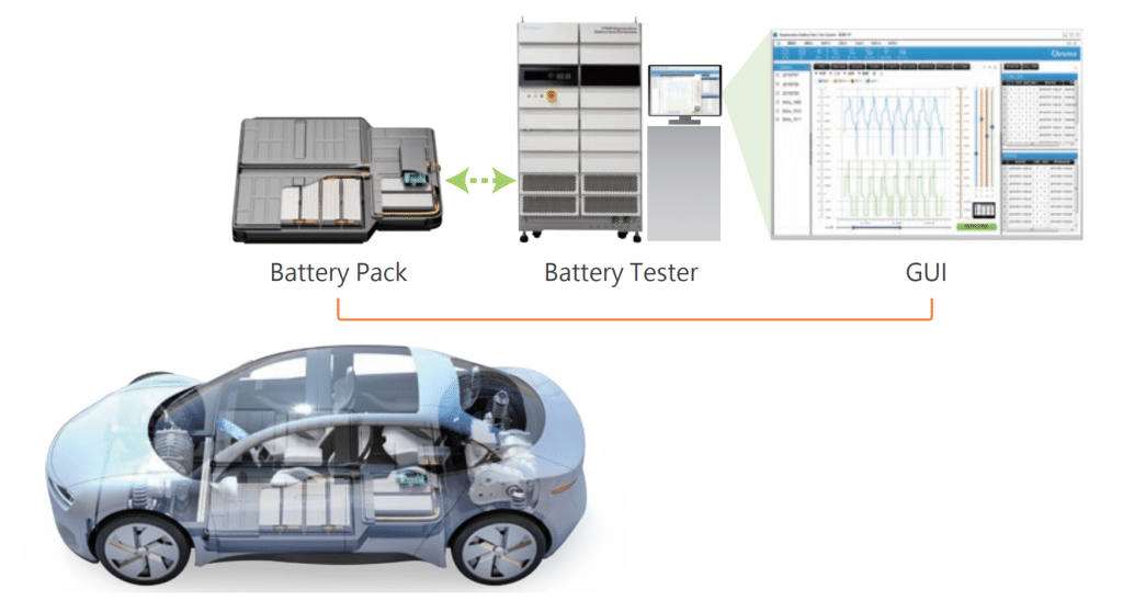
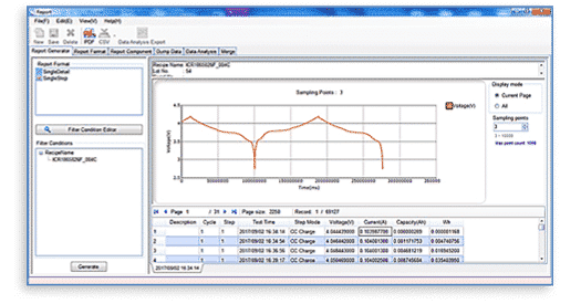
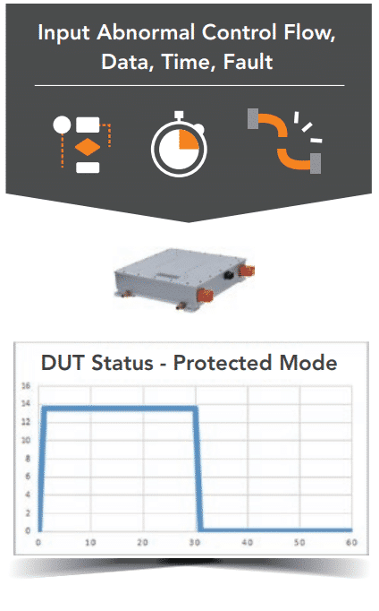
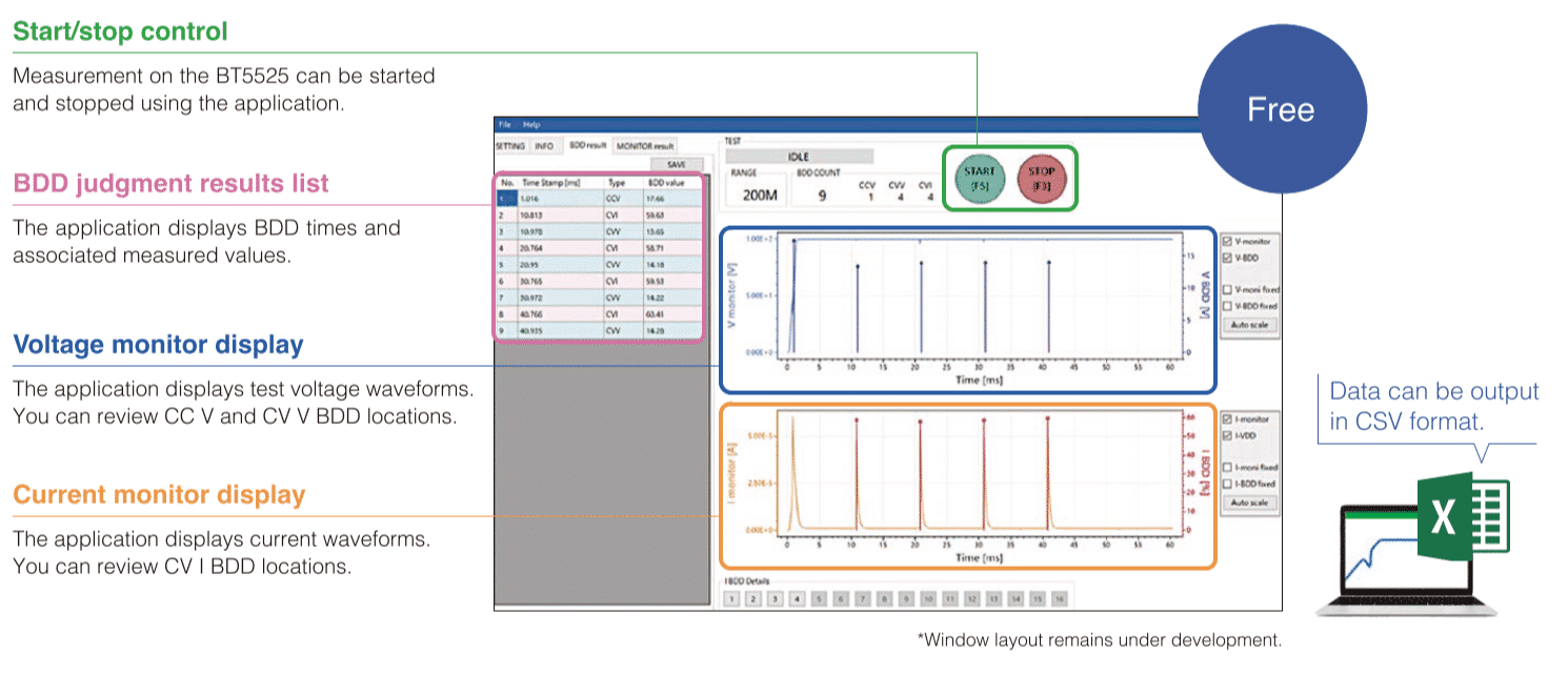
• View EUT and test data
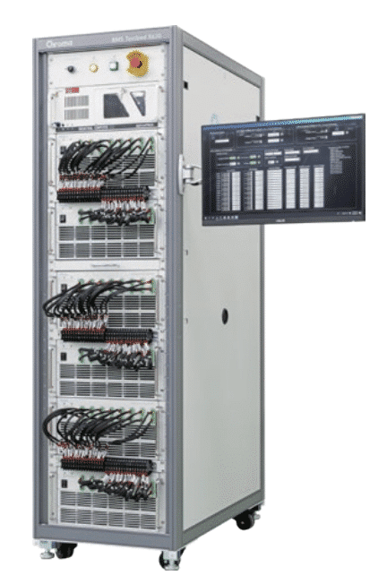
• Configure and control devices

raditeq-logo

RadiMation Pro - Pre-Certification Testing

• Up to 3 bands multiband testing
• Up to 6 GHz calibration and testing
• GTEM one EUT orientation
• Large database of device drivers

raditeq-logo

RadiMation Pro - Full Compliant Testing

• Traceable Results, backwards compatible
• up to 100 band multi-band testing
• up to 120 GHz calibration and testing
• Supports EUT controllers
• Antenna & turntable control
• Automatic report generator
• 3 x EUT orientations
• Dedicated Device Driver Development

Available RadiMation Modules

raditeq-logo

RadiMation

Pulsed Immunity testing

raditeq-logo

RadiMation

Radiated Immunity testing

raditeq-logo

RadiMation

Radiated Emission Module

raditeq-logo

RadiMation

Coducted Immunity module

raditeq-logo

RadiMation

Coducted Immunity module

raditeq-logo

RadiMation

Conducted Emission testing

What the RadiMation® Software types can offer you!

RadiMation® is available in three different varieties, each offering a different range of functionalities. RadiMation® Free giving access to  the least software aspects like existing files and other viewing types of functions. The RadiMation® PRO version is offering you full access to the full range of the powerful capabilities of RadiMation®

RADIMATION® FEATURES RADIMATION® FREE RADIMATION® ESSENTIAL RADIMATION® PRO
CONTROL INDIVIDUAL INSTRUMENTS
CREATE / OPEN / MODIFY EUT FILES
CREATE / OPEN / MODIFY TSF FILES
PRINT OR EXPORT TEST DATA (GRAPH/TABLE)
MULTI-LANGUAGE USER INTERFACE
USER DEFINABLE LIMIT LINES
CUSTOMIZABLE GRAPH LINES
RUN EMC EMISSION / IMMUNITY TEST (GENERIC EMC STANDARDS)
RUN EMC EMISSION/IMMUNITY TEST (AUTOMOTIVE, MILSTD, DO-160 STANDARDS)
GTEM EMISSION/IMMUNITY TEST (1 EUT ORIENTATION) 1 x EUT orientation 3 x EUT orientations
MAXIMUM BAND FOR MULTIBAND EMISSION/IMMUNITY 3 bands 100 bands
AUTOMATIC PEAK DETECTION AND FINAL MEASUREMENT
UNLIMITED NUMBER OF EUT MONITORING CHANNELS
USER DEFINABLE CHANGE ORDER TESTING
ATTENUATION / GAIN CALIBRATION MEASUREMENTS
AMBIENT SUPPRESSION
POLAR- AND HEIGHT PLOT OF EMISSION MEASUREMENTS
SEQUENCE TESTING
MAXIMUM FREQUENCY FOR CALIBRATION AND OR TESTING 10 GHz 120 GHz
SUPPORT 3RD PARTY VIDEO MONITORING SYSTEMS
SUPPORTS FOR EUT CONTROLLERS
GTEM EMISSION/IMMUNITY TEST (3 EUT ORIENTATIONS, OATS CORRELATION)
SUPPORT AUTOMATIC REPORT GENERATOR
CONTROL ANTENNA TOWER/TURNTABLE
CONTROL RF SWITCH MATRIX SYSTEMS
DEDICATED DEVICE DRIVER DEVELOPMENT

Why choose RadiMation?

RadiMation® supports the engineer

EMC test engineers are highly skilled and highly experienced people. In terms of motivation and costs, it is important that engineers do not suffer from “tedious work” such as:

  1. Monitoring the behavior of the EUT
  2. Manually enter test data into the test report
  3. Keeping track of test data
  4. Reconfigure the test repeatedly

RadiMation offers solutions for all these activities so that the test engineer can fully focus on EMC testing.

Fully automated EMC testing

Rather than automating just a few EMC tests. RadiMation® EMC software has been developed in close collaboration with external companies such as EMC accredited laboratories. At the heart of this package is a closed loop system optimized for fast and accurate measurements. This package supports any brand of EMC test equipment, all standards such as civil, automotive, military and aerospace, while test results can be easily exported. Tests that are performed regularly can be defined and run in series without the intervention of an engineer. All these functions together with the control of the device under test (EUT) and the fully automated generation of EMC test reports make fully automated testing a reality.

Supports all industries & international EMC standards

RadiMation® supports every EMC test standard with a single software package!. This includes commercial, military and automotive EMC testing standards. Currently, the RadiMation EMC test software is used in the following industries:

  • Automotive
  • Business electronics
  • Telecom equipment
  • Technical Universities
  • Medical equipment
  • Defense/military equipment
  • Consumer electronics
  • Industry (machines, systems and installations)
  • R&D testing laboratories
  • Independent Accredited Labs

Traceable results

ISO/IEC 17025 requires measurements to be traceable. Quality control and subsequent error control require that not only the final test results are stored but also all raw data. In the case of an unexplained phenomenon, these raw results can be retrieved to study and clarify what caused the issue and whether this event affected the pass / fail statement by recalculating the raw data.

Automated report generation

Since all test related information is stored in the RadiMation® EMC testing software, the report is generated fully automatically. Based on a template using RadiMation® keywords, each organization can stick to its own layout and style. The test engineer only needs to add the comments and conclusion. All test information, such as pass / fail criteria, emission and immunity curves, used test equipment and EUT related data are combined by means of the standard word processor of your choice (Microsoft Word® or Excel®).

Modular

RadiMation® can be bought as a complete full package or can be purchased per module, preventing unnecessary investments. Currently the following RadiMation® modules are available:


  • Radiated Immunity
  • Conducted emission
  • Conducted Immunity
  • ESD, EFT/Burst, Surge and Dips/Interrupts
  • Radiated emissions
  • Report Generator
  • Data export

Data export

Generated data can be exported in many ways. Cut and paste, export to Excel format or in a comma separated file are ways to achieve maximum flexibility and take advantage of the obtained results.

Quality

Conducting EMC immunity tests can be a time consuming process. Therefore, in the RadiMation® EMC test software package, the control of test instruments is optimized to the level where dwell time at each frequency point becomes the only limiting factor. The emissions test modules are optimized for efficiency and peaks are automatically detected.

Optimized for effective EMC testing

RadiMation® makes use of error checking device drivers. This means that when a command is sent to the device, RadiMation® checks that the command has been properly received and interpreted by the device. By reading back the setting from the device, RadiMation checks whether the instrument is really set to the intended value.
In addition, several system checks and tests are performed before an EMC test is started.

Flexible

The RadiMation® EMC test software is extremely flexible. By implementing a point-and-click philosophy on the one hand, the user can still adapt the software in line with his own preferences. All equipment used can be configured in separate test locations that are stored and easily retrieved and/or adopted if required. In addition, the sequence of events can be customer-specific. For example, the software can be set up to change the antenna movement first, then the turntable angle, and finally the polarization of the antenna followed by the next frequency step. This provides complete flexibility in testing with maximum test speed based on the speed of the individual instrument.

Adaptable to customer-specific EMC tests

Customer-specific EMC tests can be created using an intuitive Graphical User Interface (GUI) and stored in a so-called technical setup file (TSF) that can be retrieved and launched with just a few mouse clicks. This prevents test engineers from having to reconfigure tests repeatedly, reducing errors and improving test efficiency. The test setup files can be executed in series (sequence) so that multiple EMC tests can be started without the intervention of an engineer. Sequences can be saved and retrieved for future use. In addition, the information only needs to be entered into the RadiMation® EMC software once, which improves speed and reduces the risk of errors.

User friendly

All test modules in the RadiMation® EMC test software have the same appearance and use (Look and Feel). As a result, an engineer who is used to one module will quickly become comfortable with the other modules. For each module, all relevant settings and test information are displayed in one window as much as possible. This gives the technician a clear overview of how to perform the test and what settings to use for a certain EMC test.

Site license

A site license is available for large organizations requiring more than four full RadiMation® packages. This offers the customer a cost-efficient solution for one or more large sites.

Investment protection

Raditeq’s pricing plan is designed so that the customer only pays the difference between the initial investment and the upgrade situation. In this way, the customer is not forced to make unnecessary or premature investments.

Truly open software

With more than 5.000 drivers available, RadiMation® supports all commercially available EMC equipment from all brands (*). The number of device drivers is growing every day. Still no driver available? The RadiMation® team will develop one at no additional cost. This makes RadiMation® truly open software that can be used with any setup. This way your organization is not tied to equipment from one manufacturer.

RadiMation® support equipment uses GP-IB, LAN, USB or RS-232 interfaces.

(*) Raditeq supports all commercially available EMC equipment that is still supported by the original manufacturer. Moreover, many device drivers are available for legacy equipment. Check here whether all drivers for your current setup(s) are available.

Additional information

Radimation Wiki – For support and guiding information about RadiMation.

RadiMation Forum – For the latest RadiMation news and updates Free RadiMation Test – Raditeq offers a free EMC software RadiMation test

Resellers – Click here for the RadiMation Resellers.

Downloads – Click here to download the RadiMation and other Raditeq Data sheets & Brochures.

System requirements

The RadiMation® software makes extensive use of data calculations, bus interactions (to control the test equipment) and screen interactions (to use graphs). Therefore the performance of the processor is very important and a dedicated PC for RadiMation® is required. Running other programs on the same computer can cause compatibility issues and is not supported. Supported programs are those used by RadiMation®, such as Word, Excel and MySQL.

The following hardware configuration is required to fully use the software:

  • Processor type: minimum 2 GHz,> 3 GHz recommended
  • Free RAM: minimum 1 GB, more than 2 GB recommended
  • Free space on the hard disk: minimum 1 GB
  • Monitor: SXGA (1280 x 1024) or larger (minimum 1280 pixels wide and minimum 900 pixels high)
  • IEEE Card: Any GPIB card supported by the National Instruments NI-488.2 Software Library

New USB RF Power Meters – RadiPower

RF Power Meters

The RadiPower Series consists of different USB Power meters. These power meters are capable of measuring at different speeds and frequency. The RadiPower® Power Meters are easily connected to your setup through the USB connection on the back. Designed to perform, Pulsed, AM, FM, tracing modes and peak power measurements the RadiPower® Power Meter can be used in different test environments.

RadiPower USB Power Meter

RadiPower® Models

Product NameApplicationsFrequency RangeMeasurement SpeedMeasurement RangeDetails
RadiPower RPR4006RTrue RMS Measurements4 kHz – 6 GHz5 MS/sMax. 10
Min. -70
More Details
RadiPower RPR3008WRMS power
peak max hold
Burst mode
10 MHz – 8 GHz10, 50, 100 kS/s,
1, 5, 10, 20, 33 MS/s
50 dBm to +10 dBm @ 10 MHz to 6 GHz
-40 dBm to +10 dBm @ 6 GHz to 8 GHz
More Details
RadiPower RPR3006WRMS power
peak max hold
Burst mode
10 MHz – 6 GHz10, 50, 100 kS/s,
1, 5, 10, 20, 33 MS/s
-50 dBm to +10 dBm @ 10 MHz to 6 GHzMore Details
RadiPower RPR2018CCW Measurements80 MHz – 18 GHz20 kS/s
100 kS/s
1 MS/s
-45 dBm to + 10 dBm (Usable to -50 dBm)More Details
RadiPower RPR2018PCW power
Peak power
Envelop tracing
80 MHz – 18 GHz20 kS/s
100 kS/s
1 MS/s
-45 dBm to + 10 dBm (Usable to -50 dBm)More Details
RadiPower RPR2006CCW Measurements(4 kHz) 9 kHz to 6 GHz20 kS/s
100 kS/s
1 MS/s
-55 dBm to + 10 dBm (Usable to -60 dBm)More Details
RadiPower RPR2006PCW power
Peak power
Envelop tracing
(4 kHz) 9 kHz to 6 GHz20 kS/s
100 kS/s
1 MS/s
-55 dBm to + 10 dBm (Usable to -60 dBm)More Details

RadiPower® Models

MODE 2000C SERIES 2000P SERIES 3000W SERIES 4000X SERIES
CW MODE
PEAK MODE
ENVELOP TRACING MODE
BURST MODE
TRUE RMS MEASUREMENT

The RadiPower® is an EMC/RF power head designed for CW power measurements during EMC testing. A range of power heads are available for measuring RF power from 4 kHz to 18 GHz. The RadiPower is a fast and accurate RF power head with a USB interface for easy connection. The RPR2006C covers a frequency band from 4 kHz to 6 GHz and can perform measurements with an accuracy of 0.15 dB. The RPR2018C covers a frequency band from 80 MHz to 18 GHz and can perform measurements with an accuracy of 0.2 dB. This series of heads enables effective immunity measurements in accordance with EMC standards.

Plug in card

The RadiPower® RF power head can be connected to a USB1004A plug-in card using USB connectors. This plug-in card supports up to four RadiPower® heads, allowing forward and reflected power measurements from two amplifiers with just one instrument. The plug-in card fits into the RadiCentre® EMC measurement system, which is available in a version with 1 slot (CTR1001S), 2 slot (CTR1004B) or 7 slot (CTR1009B).

Wide Band

Two models cover a frequency band from 4 kHz to 18 GHz, the RadiPower® is a perfect product for all EMC measurements, including military, automotive and  EMC immunity tests for CE marking. The RadiPower 6 (model RPR2006C) has a standard frequency range from 9 kHz to 6 GHz and covers most conducted and radiated sensitivity tests. The 4 kHz low frequency extension (option # 010) allows the RPR2006C to be used from 4 kHz, as required in MIL-STD-461 CS-114, BCI common mode test on power cables. The RadiPower 18 (model RPR2018C) covers power measurements from 80 MHz to 18 GHz.

High dynamic range

The RadiPower® RPR 2006 offers a dynamic range of > 65 dB and the RadiPower® RPR 2018 offers a dynamic range of > 55 dB, making them ideally suited for all typical immunity applications and standards.

Standalone

The RadiPower control head can also be used in a stand-alone configuration. In that case, the power head is connected directly to a PC by means of a USB cable, the measured power levels are displayed on the PC using the RadiMation® Free monitoring program (download free of charge).

High precision

The RadiPower® measures with an accuracy of 0.15 dB (RPR2006C) or 0.2 dB (RPR2018C) over the full band and therefore offers the perfect solution for testing according to EN61000-4-3 / -6 or ISO / IEC 11452-2 / -3 / -4 / -5 / -7.

Immunity Applications

Immunity applications require the field or power to be measured accurately. Actual fields can be measured with the RadiSense® LASER powered E-field sensor. Likewise, the RadiPower® is able to measure power levels. Often, both forward and reflected power must be measured. Since the RadiPower® USB1004A plug-in card can control up to four heads, the RadiPower® solution is ideal for EMC power measurements.

New Raditeq – RadiSense E-field Probes!

Importance of accurate measurement

During immunity testing, the accuracy of the overall test setup depends solely on the E-field probe. As such, accuracy mainly determined by isotropy, is of the utmost importance. Over the years, Raditeq’s development team has been committed to developing probes with increasing accuracy.

RadiSense Set

RadiSense® Models

Product NameApplicationsFrequency RangeMeasurement SpeedMeasurement RangeGet Quote
RadiSense® RSS2040SCE Marking
Anechoic Chamber
10 MHz – 40 GHz100 Measurements /s1 V/m – 1000 V/mGet Quote
RadiSense® RSS2040HCE Marking
Reverb Chamber
10 MHz – 40 GHz1000 Measurements /s1 V/m – 1000 V/mGet Quote
RadiSense® RSS2026SCE Marking
Anechoic Chamber
10 MHz – 26 GHz100 Measurements /s1 V/m – 1000 V/mGet Quote
RadiSense® RSS2026HCE Marking
Reverb Chamber
10 MHz – 26 GHz1000 Measurements /s1 V/m – 1000 V/mGet Quote
RadiSense® RSS2010ICE Marking
Anechoic Chamber
9 kHz – 12.5 GHz100 Measurements /s0.1 V/m – 750 V/mGet Quote
RadiSense® RSS2010SCE Marking
Anechoic Chamber
20 MHz – 12.5 GHz100 Measurements /s0.1 V/m – 750 V/mGet Quote
RadiSense® RSS2010BCE Marking
Reverb Chamber
9 kHz – 12.5 GHz1000 Measurements /s0.1 V/m – 750 V/mGet Quote
RadiSense® RSS2010HCE Marking
Reverb Chamber
20 MHz – 12.5 GHz1000 Measurements /s0.1 V/m – 750 V/mGet Quote
RadiSense® RSS2010ECE Marking
Reverb Chamber
20 MHz – 10 GHz15 Measurements /s0.5 V/m – 200 V/mGet Quote
Essential SeriesPre Certification
Anechoic Chamber
20 MHz – 10 GHz15 Measurements /s0.5 V/m – 200 V/mGet Quote

Importance of accurate measurement

Since then, the Raditeq development team has been continuously improving its product, the application of the spherical shaped probe proves just that.

Continuous improvement requires constant research. Raditeq built its own special e-field test room to research the isotropic behaviour of e-field probes. Staggering results presented that the isotropic behaviour of e-field probes available on the market are far inferior than expected. The RadiSense 6, by no means the worst probe, was no exception. Using the knowledge gained from numerous measurements, our team took on the challenge of building a probe with better isotropic behavior.

At the beginning of 2020, this resulted in the RadiSense® 10, the probe with the best isotropic behavior available in the market.

Internal calibration data

By default, the factory linearity adjustment data is stored inside the probe. In addition, the frequency response correction data for all three axis, which is obtained from an accredited calibration laboratory, can be stored inside the probe as user correction. Due to this internal correction, there is no need to apply frequency dependent corrections for individual axis’ in software anymore. This results in a high accuracy and ease-of-use.

E-field probes, their size matters!

Additionally, the RadiSense® 10 is inherently small, making it perfect for (G) TEM cell measurements. For measurements in (G) TEM cells, the size of the probe is even more important. If compact cells are used, substantial errors will occur with an E-field probe that is relatively large to the dimensions of the cell. To obtain reliable and accurate measurement results, the EMC probe must be small, isotropic and fast. The RadiSense® 10 offers all these aspects and is therefore the most reliable choice for an E-field probe. 


Battery Free

Battery powered probes present many disadvantages as opposed to laser powered probes, these include; influence of galvanic wires on measured E-field, battery drainage and limited overnight testing. Unlike other probes, the RadiSense® E-field probe is powered by a high-performance laser, whose light is sent to the probe via a fiber optic cable and feeds the low-noise amplifier and a single microprocessor chip, reads the antennas and transmits the measured values to a PC via a second fiber optic cable.

Unprecedented accuracy

A small electric field probe is essential for measurements in a uniform field of an anechoic chamber. In the past it was commonly agreed upon that smaller probes provide for more accurate measurement. Controversially, later findings show that the position of the probe is of equal importance to the accuracy and reliability of the measurement. When the probe rotates in the anechoic chamber, the measurements will vary and may present values that differ considerably to those that are actually present. Needless to say that this process is detrimental to the final data. The RadiSense® 10 offers the perfect solution to this problem. With six antenna elements, this probe offers an unprecedented isotropic response. Regardless of its position or its angle, the radiation and its reflections reach the probe.

Software Support

The RadiSense® E-field strength sensors are supported by RadiMation®, the automated EMC measurement software. The RadiMation® Free software is included with the system for stand-alone use. The RadiSense® can also be controlled by third party software as all control codes are available.

Operation Software

The RadiSense® Series can be operated by the RadiMation® software with which you can use your Electric Field Probe with ease. Next to RadiMation® the RadiSense® 10 can be used with EMC32 Software. You can find the needed configuration and format specification here.

EMC32

  • RadiSense® Device Configuration – Download

  • RadiSense® Format Specifications – Download

Note: This EMC32 Driver for the RadiSense E-Field Probe is only usable in combination with a RadiCentre Slim using a USB communication connection.

BATTERY INSULATION TESTER BT5525

Detect contamination that could cause defects. Improve battery cell productivity through high-speed testing.

To ensure the longevity and reliability of batteries, it is important to identify and address the root causes of latent defects during the production testing process. Small insulation defects, if left unchecked, can have a significant impact on the overall service life of a battery and increase the risk of fires. Two primary factors that contribute to insulation defects are contamination with metallic particles and small scratches that occur during the manufacturing process. By identifying and addressing these issues early on, we can ensure that the batteries produced meet the necessary quality standards and provide safe and reliable performance.

The BT5525 can prevent the shipment of batteries with latent defects that could lead to fires.

High-speed testing to increase production volume. Easy to add instruments while saving space. Invest in quality at a reasonable cost.

Ideal for insulation resistance testing before battery electrolyte filling

The BT5525 conducts insulation testing between electrodes prior to filling the cells with electrolyte, with a maximum test voltage of 500 V. Under specific test conditions, it also facilitates insulation testing between module/pack electrodes and the enclosure.

Detecting minuscule insulation defects caused by contamination (Break Down Detect function)

The proprietary BDD testing function is designed to detect even the smallest internal short-circuits caused by contaminants, such as metallic matter, before the battery cells are filled with electrolyte. By catching defective parts early on in the production process, the BDD helps reduce the risk of fires and accidents caused by overheating after the battery is shipped. Moreover, these tiny internal short-circuits can speed up battery degradation. By using the BDD function, the production of batteries with improved durability and electrical performance can be achieved.

Stable insulation resistance testing, even in noisy environments

Hioki utilized its extensive design expertise and insulation resistance tester measurement technology to successfully minimize the impact of external noise. This has led to the BT5525 delivering stable and consistent insulation resistance testing with a level of precision that allows for the detection of internal short-circuits caused by contamination.

Preventing testing do-overs due to erroneous judgments

The BT5525 offers a contact check function to verify that proper contact has been made with the circuit being tested. This is accomplished by measuring the capacitance between the measurement terminals, which includes both the stray capacitance and the capacitance of the circuit itself.

Ideal for insulation resistance testing before battery electrolyte filling

The BT5525 performs insulation testing between electrodes prior to the cells being filled with electrolyte, with a maximum test voltage of 500 V. In certain conditions that meet the requirements, it can also conduct insulation testing between the module/pack electrodes and the enclosure.

Shorten cycle times with a maximum charging current of 50 mA

The BT5525 boasts fast charging capabilities of up to 50 mA and rapid discharging of residual charge at 40 mA, significantly enhancing its charging and discharging performance.


This results in a boosted testing speed, with charging being approximately 25 times faster and discharging 4 times faster compared to earlier models. By doing so, it shortens the insulation resistance testing time for batteries, which are increasingly being produced with higher capacities.


*In comparison to Hioki’s INSULATION TESTER ST5520.

Compact footprint makes it easy to integrate the BT5525 into other systems

With its extensive product design expertise, Hioki has achieved high performance in a compact form factor. The instrument can be integrated into testing systems, thereby reducing their size. This enables manufacturers to utilize compact testing systems, maximizing limited production space.

Invest in quality at a reasonable cost

The BT5525‘s functionality and performance make it a cost-effective solution, as it was designed with careful consideration given to the specific requirements of battery insulation resistance testing.


A dedicated PC application allows for the monitoring of voltage and current fluctuations during testing.


The instrument has the ability to output a test voltage of up to 500 V, making it suitable for insulation resistance testing on batteries of all sizes, from the large batteries used in electric vehicles to small battery cells.

PC application for analyzing waveforms

Hioki offers a free PC application that allows for the examination of voltage and current fluctuations. The capability to view waveforms can be beneficial when evaluating test results and setting judgment reference values for testing lines.

Additionally, since data can be outputted in the CSV format, waveforms can also be reviewed using other applications, such as Excel.

Options

CLIP TYPE LEAD L2130

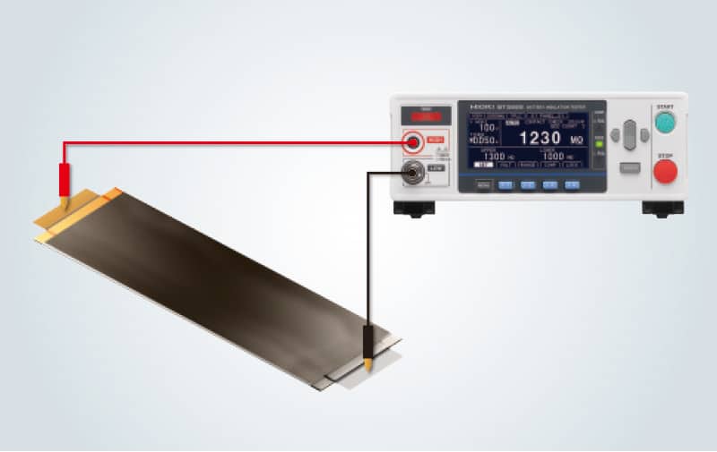
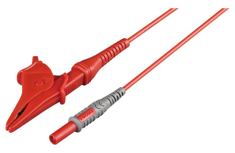
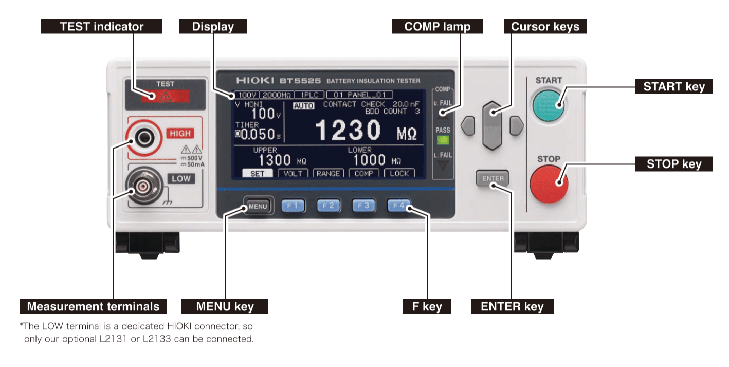
For HIGH terminal, banana / alligator clip, red, cord length 1.5m

CLIP TYPE LEAD L2131

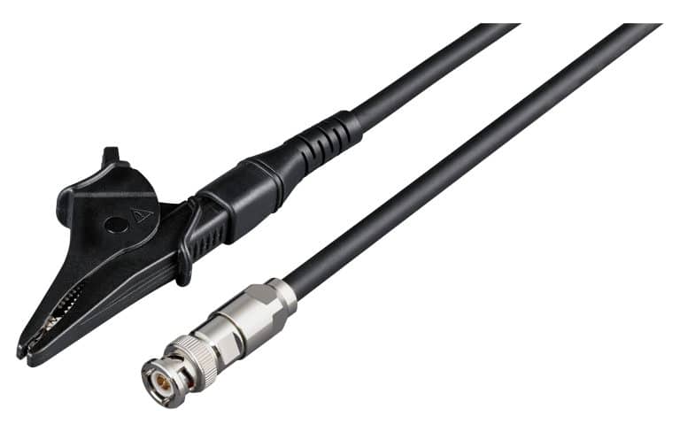
For LOW terminal special triaxial / alligator clip, black, cord length 1.5m

OUTPUT CORD L9094

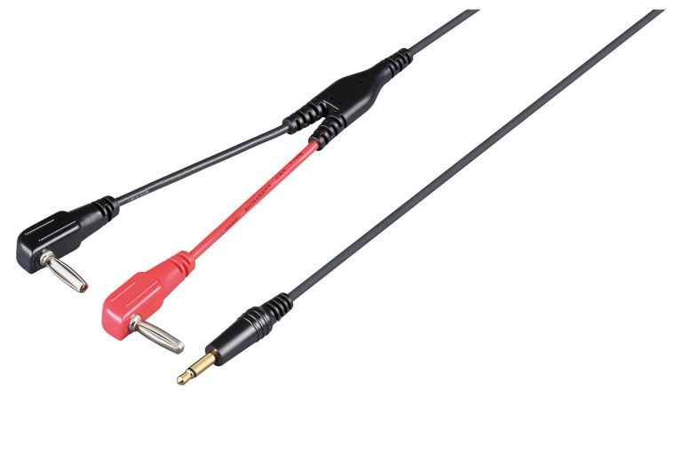
For analog output, banana plugs (red, black), cord length 1.5m

UNTERNIMINATED LEAD L2133

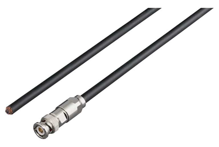
For LOW terminal, special triaxial / cut wire, black, cord length 5m

UNTERMINATED LEAD L2132

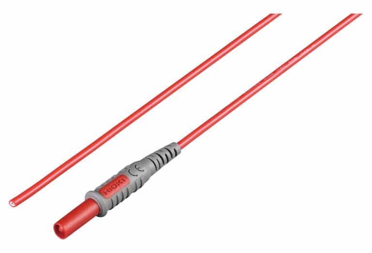
For HIGH terminal banana / cut wire, red, cord length 5m

UNTERMINATED LEAD L2132

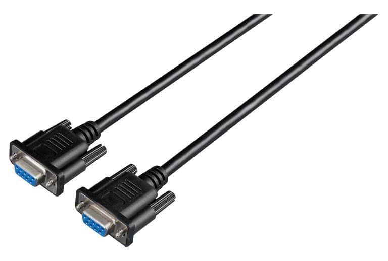
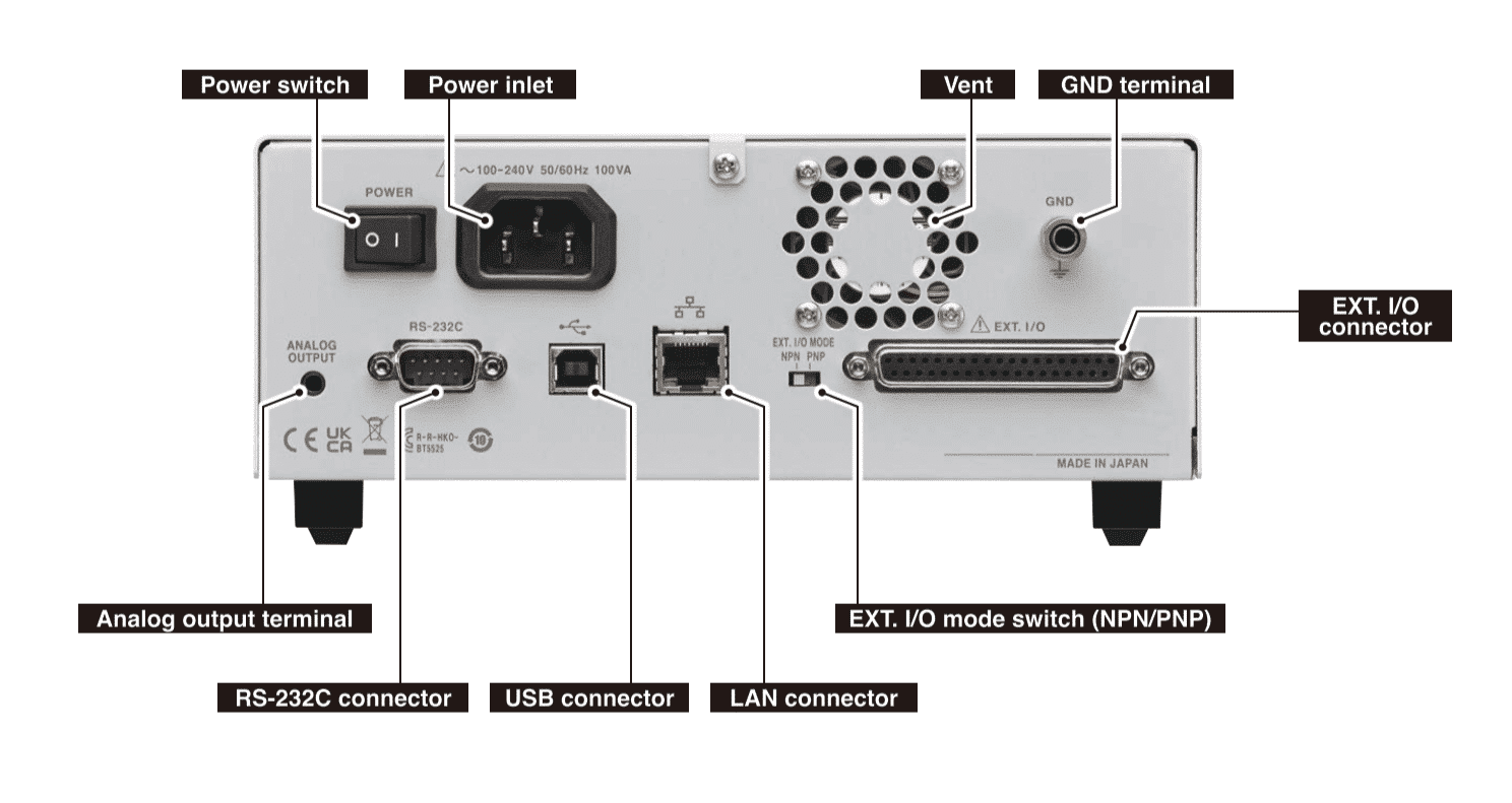
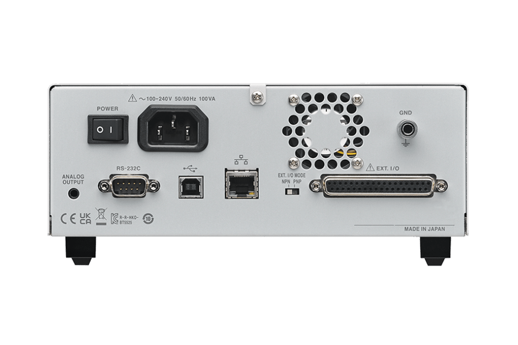
For external control, double shielding, 9-pin / 9-pin, cord length 3m

Key Features

Contact check function reduces the number of false negatives caused by equipment issues.

BDD function for detecting minuscule short-circuits caused by contamination before batteries are shipped.

High cost performance thanks to accessible pricing, high-speed testing, and compact footprint.

Stable insulation resistance testing even in noisy environments.

Ideal for battery production lines.

Product Video

Dimensions and mass

215 mm (8.46 in) W × 80 mm (3.15 in) H × 306.5 mm (12.07 in) D, 2.8 kg (98.8 oz)

Using AR functionality

Scan the QR Code to the left on your Android or iOS device to access this page. Then select the AR button in the 3D model area to start your AR experience.

[ Precautions ] What you see in AR may differ from the actual product in terms of characteristics like size, colors, and materials. The following operating systems and browsers are recommended. [ iOS ] Safari on iOS 15 or later [ Android ] Chrome on Android 12 or later (AR enabled device)

To assure battery quality over the long term, it’s necessary to detect the causes of latent defects in testing processes on production lines. Minuscule insulation defects can eventually degrade battery service life and cause fires. The principal causes of insulation defects are contamination (with metallic matter) and minuscule scratches occurring in production processes.

The BT5525 can prevent the shipment of batteries with latent defects that could lead to fires.

This is introduction to the functions of the new “BATTERY INSULATION TESTER BT5525” for battery production lines. The BDD function, which monitors minute voltages and currents and detects foreign substances mixed in the production process, and a convenient PC application that allows you to view waveforms, will be explained while actually measuring!

Interface

Front Interface

Back Interface

External control and other communications interfaces

The BT5525 ships standard with LAN, RS-232C, and USB interfaces, allowing it to be connected to a PC or programmable logic controller (PCL). This capability can be used to control the instrument and retrieve test results.

Furthermore, the instrument provides external I/O terminals to facilitate instrument control and retrieval of instrument status and judgment results.

Accurately Measure High Voltages up to 5000 V in a Variety of Applications with the new Hioki VT1005

The new Hioki VT1005 high voltage divider accepts input voltages up to 5kVrms /4MHz for accurate power measurements

In order to meet the continuous need for more electrical power, there is a trend to introduce higher system voltages in a wide range of applications. One particular application is the accurate efficiency measurement of railways, trucks and busses that are operating at voltages higher than 1000V. Accurate power loss measurement of inductive components used in HV power electronics is another interesting application.

Engineers prefer to measure the loss in these devices under real-life conditions and the very low power factor of these measurements requires a phase error compensation to achieve accurate measurements. This can be discovered with the Hioki High Voltage Divider.

SiC semiconductors are increasingly used for high-voltage applications with switching frequencies of 50kHz or higher. The VT1005 High Voltage Divider is the only solution on the market today that is designed to provide accurate results even at these high switching frequencies.

The VT1005 High Voltage Divider provides the best solution for accurate power measurement up to 5kVrms and 4MHz in combination with the Power Analyser PW8001.

Hioki VT1005 High Voltage Divider Highlights

  • Input Voltage up to 5kVrms / 7.1kVpeak
  • Voltage dividing ratio is 1000:1
  • Measurement bandwidth 4MHz
  • Identical gain and phase characteristics for each divider
  • Phase error compensation with PW8001 (firmware version 1.3 or higher)
  • Excellent frequency flatness needed for high‐efficiency inverter measurements

Learn more about the Hioki VT1005

To talk to a member of our team about the new Hioki VT1005,
call us on +44 (0)1462 431 981.

Amplifier buyers guide

BONN Elektronik Solid State Amplifiers

MDL offers a wide range of Solid State Amplifiers that cover ranges from 4 kHz up to 47 GHz with a usable power rating of between 1mW – 20 kW. 

MDL is the UK distributor for BONN-Elektronik. BONN-Elektronik has been in the RF components and systems industry for more than 40 years. All of its components and products comply with CE standards and VDE safety regulations.

Modular

The core competence of BONN Elektronik products is based on a modular platform concept. This allows flexible customized power amplifier solutions perfectly addressing the customers’ requirements without involving any additional non-recurring engineering cost!

Solid State Amplifiers

Solid State

The covered frequencies start at 9 kHz and range up to 40 GHz. At the low end of the frequency range, up to 20 kW of output power is available. From 26.5 to 40 GHz still, 40 W of broadband power is provided. This wide range is realised in different technologies where most of the amplifiers are based on solid-state technology.

BLMA Series Solid State Amplifiers

Hybrid

At low frequencies with corresponding very high power levels, solid-state amplifiers are supplemented by so-called distributed tube amplifiers. These distributed amplifiers are well known for high tolerance against poor VSWR of antennas available for low frequencies.

Hybrid Amplifiers

TWT

Broadband power available in solid state technology declines rapidly above 1 GHz.
Therefore, traveling wave tubes are used for higher output power levels. Up to 18 GHz output power levels of 1 kW cw and 8 kW pulsed are provided.

Pulsed Amplifiers

Test Solution for lithium batteries with ultra-low DC internal resistance

Internal resistance is a critical parameter that determines lithium-ion battery power capability, energy efficiency, and heat generation. It is also an important indicator of the state of health (SoH) of the batteries, which influences the design of electric vehicle acceleration, fast charging, and cooling systems (EVs). Furthermore, the Battery Management System (BMS) must establish an internal resistance model to accurately manage the power capability to avoid battery abuse and improve battery safety and service life. As a result, research on internal resistance and power capability is critical in the development of next-generation battery cells and the optimization of battery systems. However, as a cost-cutting measure, manufacturers are increasingly adopting ultra-low DC internal resistance and enlarging single-cell designs. However, as manufacturers adopt ultra-low DC internal resistance and enlarge single cell designs to improve electric vehicle power density, general equipment is increasingly unable to deliver the required test current of thousands of amperes, leaving test engineers with a limited choice of expensive equipment.

Nowadays, battery internal resistance measurement technique is mostly separated into two types: 1) Pulse (step) current is generally utilised to measure the potential difference, which is then used to calculate the internal resistance value. 2) Electrochemical impedance spectroscopy (EIS) using disturbance spectrum technology is used to evaluate AC resistance. The battery’s complicated electrochemical characteristics prevent direct comparison of the DC resistance and AC impedance. The two measurement techniques are complementary due to the difference in the analyses’ time domains and are mostly selected according to the application conditions.

In the design of electric vehicles and energy storage systems, pulse current is frequently used to test DC internal resistance. In addition to the short test time, research has shown that current amplitude affects the internal resistance of the battery [1] and that the high-current pulse test more closely approximates real load applications. The VDA current step method [2] and the Hybrid Pulse Power Characterization (HPPC) test [3] [4] are internationally standard methods for pulse current testing, with pulse widths ranging from 100mS to 30S.

Depending on the measurement timescale, the voltage drops are influenced by various internal resistance phenomena: ohmic resistance of the transient voltage drop, equivalent capacitance and interface electric charge transfer resistance during the first few seconds of the voltage drop, and polarisation resistance of slower response due to ion diffusion (Figure 1). The total resistance is calculated using the pulse test results. It should be noted that a wider pulse width may change the state of charge (SOC) and cause additional voltage drops, resulting in internal resistance measurement deviations. A too-small pulse amplitude, on the other hand, will result in a significant increase in measurement uncertainty. Errors in current/voltage measurement and temperature control can also cause measurement errors.

(Figure 1) The relationship between DA pulse test voltage change and battery internal resistance equivalent circuit

The internal resistance and power characteristics of the battery are calculated during USABC HPPC tests by subjecting battery cells to 10~30S of maximum pulse discharge and 10S of maximum pulse charge under different SOCs to measure the change in electric potential. According to this principle, if a 60Ah lithium battery cell needed to have its pulse working current (10C-rate) tested ten times, 600A charging and discharging equipment was required. But not anymore, because Chroma now offers a 200% pulse current test solution!

The Chroma 17010H has a single channel current capacity of 300A, which can be amplified with Super Mode to output 200% current (600A) in 30 seconds, making it ideal for pulse current performance testing. The new design prioritises battery applications and optimises the power output mode, resulting in a 50% smaller footprint and a 30% lower price (Figure 1).

The temperature control of the power circuit is critical to Chroma’s high pulse current capability. For starters, the 17010H’s high-conversion-efficiency energy recovery architecture significantly reduces component heating during charging and discharging. Second, by optimising power module integration and component selection, it increases operating current. Finally, a heat flow design is used to control temperature. In terms of measurement, a distributed high-precision current transformer structure ensures current accuracy, and a cold and hot area circuit layout reduces temperature drift, resulting in an integrated battery test system with a 200% pulse current output.

(Figure 2) The benefit of 200% pulse current Mode

The following are the primary benefits of Chroma 17010H:

  • High measurement reproducibility saves testers time on trend judgment and characteristic analysis.
  • Zero-crossover and fast current response capabilities, test results closely resemble real-world applications.
  • With a minimum current range of 1:10 and suitable ranges for both high and low-rate performance tests, the multiple current range design improves the accuracy of small currents.
  • A 75% discharge energy recycling efficiency not only saves operating power and reduces waste heat from air conditioning, but also reduces laboratory power distribution requirements.
  • Independent Level 2 V. Protection function improves high current testing safety.